Author: Dave Williams; dlwilliams=aristotle=net
You could work on the column while it's mounted to the machine, but like the table conversion, it's easier if the column is dismounted and laying on the bench.
1) Remove the three hand levers on the column feed
2) Remove the two screws that hold the sheet metal cover over the fine feed
3) Remove the two Allen screws on the fine feed and the two on the pinion block. Remove the feed assembly and set it aside.
4)loosen the gibs
5) Remove the acorn nut on the counterbalance, then remove the counterbalance arm by wiggling it from side to side. You might have to pry slightly to get it off its shaft.
6) Unscrew the stud the counterbalance arm slid on, then pull off the spring and plastic sleeve
7) Remove the three screws and the metal cup
8) Remove the Allen screw and nylon bushing at the top of the column
9) Slide the head off the column and set it aside
10) Remove the rack from the column
11) Put the column aside for cleaning. There's a plastic cap glued onto the top of the column; I popped mine off so I could get in there to clean
12) Remove the four allen screws that hold the two halves of the head together.
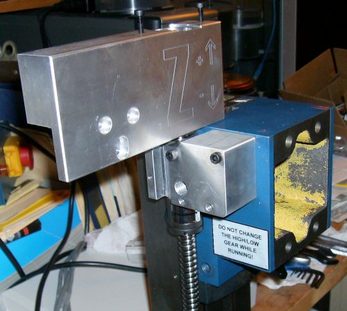
 This is the CNCFusion Z-axis kit as delivered. You removed the white
plastic stop at the top of the column and put the motor mount on. You
need to drill through the column to put bolts and nuts in the two top
holes, no big deal.
This is the CNCFusion Z-axis kit as delivered. You removed the white
plastic stop at the top of the column and put the motor mount on. You
need to drill through the column to put bolts and nuts in the two top
holes, no big deal.
The bracket is very hefty, but that's because they used a single thick piece of aluminum and carved the backside out to get the offset they wanted.
The ballnut bracket uses two small Allen screws going into tapped holes that held some of the fine feed bits. There's a 13mm (?) Allen bolt coming through a large hole in the side of the headstock, into threads in the backside of the block.
This is all well and good, and other than drilling the two holes, it's a snap to install. Unfortunately, it has a major problem - for whatever reason, CNCFusion positioned the ballscrew and bracket over the four Z gib screws. I have been unable to figure out any rational reason why.
You might conceivably cut down an Allen wrench and get to the two bottom screws, but the top two are covered by the ballnut mount. You can see the slot cut in the mount to clear the gib screws.
To adjust the gib, the entire Z-axis drive assembly has to come off, which requires removing the entire headstock, since the big 13mm bolt is only accessible from the inside (yellow) area of the headstock. You make your adjustments, put the ballnut bracket back on, then fight the now-tightened headstock over the dovetails and then reassemble the rest of the ballscrew bracketry.
No freakin' way!
 I looked at several other X2 Z conversions. The KDNTools kit puts the
ballscrew in the middle of the column, where the rack gear used to be.
The hossmachine conversion puts the ballscrew in the middle, but up above
the machine. The Syil puts "wings" around the column and puts the screw
behind the column. I saw a couple of homemade arrangements that put the
screw on the left side of the column, opposite the gib screws.
I looked at several other X2 Z conversions. The KDNTools kit puts the
ballscrew in the middle of the column, where the rack gear used to be.
The hossmachine conversion puts the ballscrew in the middle, but up above
the machine. The Syil puts "wings" around the column and puts the screw
behind the column. I saw a couple of homemade arrangements that put the
screw on the left side of the column, opposite the gib screws.
I played around with the CNCFusion bits, then eventually realized I could drill and tap some holes and mount it on the left side, assuming I made a bracket to hold the motor mount.
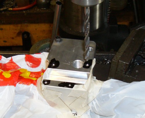
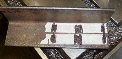
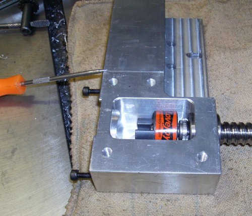
Here, the ballnut bracket is positioned and I'm punching a dimple to get
the position of one of the small mounting screws.
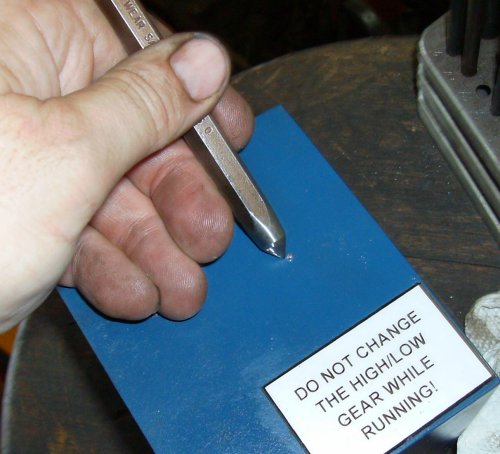 Now center punch it to guide the drill... I used center punches to locate
all the holes; it's low-tech, but simpler and faster than trying to
machine mating parts accurately.
Now center punch it to guide the drill... I used center punches to locate
all the holes; it's low-tech, but simpler and faster than trying to
machine mating parts accurately.
 Tapping drilled hole 10-32 UNC. It was simpler to use Unified National
threads since I had taps and fasteners on hand.
Tapping drilled hole 10-32 UNC. It was simpler to use Unified National
threads since I had taps and fasteners on hand.
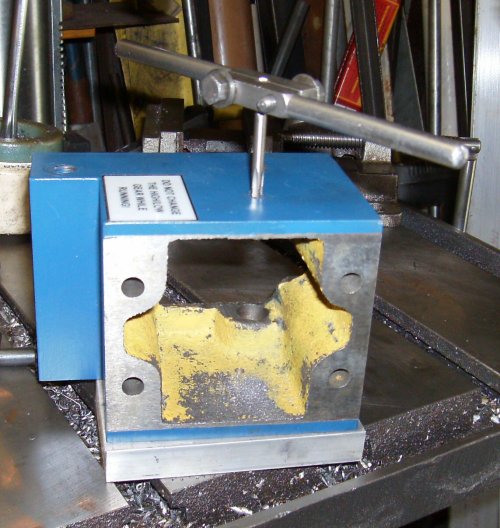
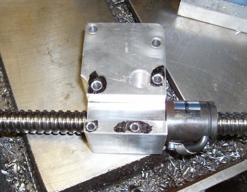
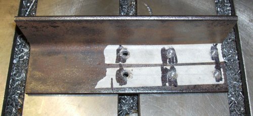
 Once I had one tapped hole to mount the block, marked off and punched for
four more mounting holes. The two right-lower holes are offset to miss
the threaded end of the ballnut inside the mounting block.
Once I had one tapped hole to mount the block, marked off and punched for
four more mounting holes. The two right-lower holes are offset to miss
the threaded end of the ballnut inside the mounting block.
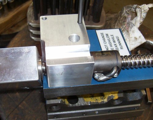
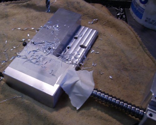
I used tape and plastic bags to protect the ballnut from chips. I did
the entire conversion without disassembling the CNCFusion bits - the only
modifications to their parts consisted of drilling and tapping a few
holes. At this point I can still remount the kit to the right side of
the headstock as they intended.
 Holes drilled and countersunk. Not much to it. The original 13mm tapped
hole will not be used.
Holes drilled and countersunk. Not much to it. The original 13mm tapped
hole will not be used.
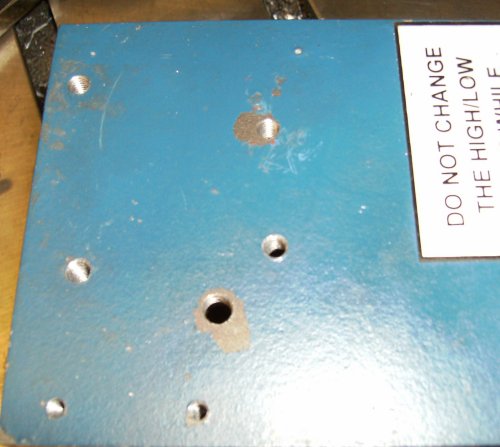 All holes drilled and tapped in the casting. The top two are 10-32 UNC,
the bottoms are 6-32. There's just barely enough metal for a countersunk
6-32 socket head capscrew's head.
All holes drilled and tapped in the casting. The top two are 10-32 UNC,
the bottoms are 6-32. There's just barely enough metal for a countersunk
6-32 socket head capscrew's head.
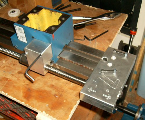
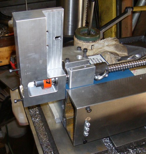
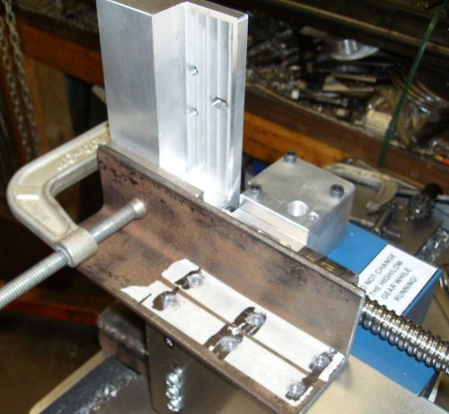
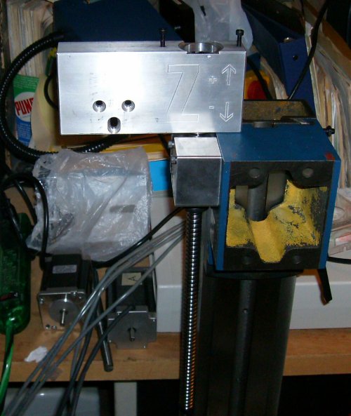 Assembly mounted to mill. Well, the ballnut bracket is; the motor mount
is just flying in the wind at the moment.
Assembly mounted to mill. Well, the ballnut bracket is; the motor mount
is just flying in the wind at the moment.
 Notice all I've done is move the whole thing to the left side. The ball
nut sits closer to the headstock and a bit farther back.
Notice all I've done is move the whole thing to the left side. The ball
nut sits closer to the headstock and a bit farther back.
I'll cut off the left side of the motor mount later. That will be the
point of no return, so I'll wait until I've tested things first!
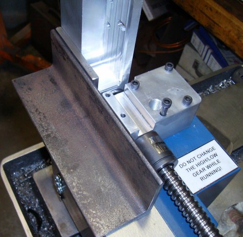
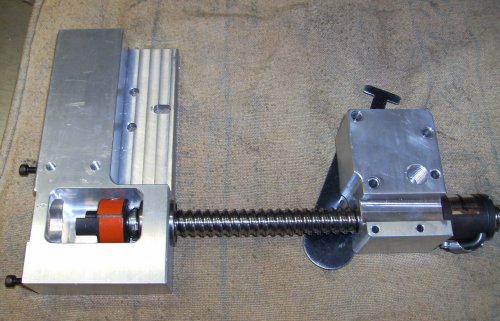
 Here's the motor bracket in its correct alignment with the ballnut bracket.
The ballscrew has the motor bracket pulled down snug against the dovetail on
the front of the column. Note the headstock goes all the way up flush to the
top of the column/bottom of the motor bracket.
Here's the motor bracket in its correct alignment with the ballnut bracket.
The ballscrew has the motor bracket pulled down snug against the dovetail on
the front of the column. Note the headstock goes all the way up flush to the
top of the column/bottom of the motor bracket.
We're going to put four bolts into drilled and tapped holes in the motor
bracket; two on the bottom, below the Lovejoy coupler, and two above the
coupler. However, since our angle iron column bracket can't reach the bottom
two holes (bottom as in this picture, right side if looking at the front of
the machine) we'll need an adapter plate to grab those two holes.
 Here are the angle bracket and spacer. I used 2"x3/16 angle, which is plenty
strong for the load. The adapter plate is 1/4" since it will need to be
tapped for 1/4" threads.
Here are the angle bracket and spacer. I used 2"x3/16 angle, which is plenty
strong for the load. The adapter plate is 1/4" since it will need to be
tapped for 1/4" threads.
The angle and adapter are in their correct positions.
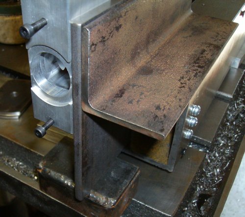 Here's another shot. The adapter plate is sitting on a piece of scrap on the
table, lined up with the top edge of the angle iron. I'll cut the bottom off
the adapter later, so it will be flush with the motor bracket.
Here's another shot. The adapter plate is sitting on a piece of scrap on the
table, lined up with the top edge of the angle iron. I'll cut the bottom off
the adapter later, so it will be flush with the motor bracket.
Note the counterbore for the stepper hangs out the sides of the motor
bracket. I'll put a notch in the adapter bracket later, for motor clearance.
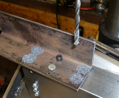
 Marking out the column mount holes. Two bolts would probably have been
enough, but there's no kill like an overkill.
Marking out the column mount holes. Two bolts would probably have been
enough, but there's no kill like an overkill.
 Holes drilled #7 through; that's tap drill size for 1/4-20.
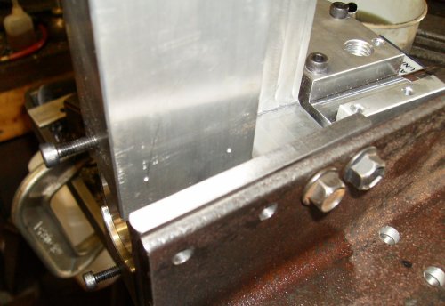
 Clamp all the parts into position. Off to the right, out of the picture, are
shims and spacers holding the ballscrew level and parallel to the column.
There will be some adjustment due to slop in the holes, but we might as well
try to start out as accurate as possible.
Clamp all the parts into position. Off to the right, out of the picture, are
shims and spacers holding the ballscrew level and parallel to the column.
There will be some adjustment due to slop in the holes, but we might as well
try to start out as accurate as possible.
 I've used the #7 center punch and punched the two center holes, drilled #7,
tapped 1/4-20, and now I've bolted the bracket down and I've drilled the other
#7 holes using the bracket as a drill jig.
I've used the #7 center punch and punched the two center holes, drilled #7,
tapped 1/4-20, and now I've bolted the bracket down and I've drilled the other
#7 holes using the bracket as a drill jig.
 There are a few steps skipped here. The two bolts you see are holding the
angle bracket and adapter plate together; it's their only purpose. I could
have welded them, but since I was drilling and tapping anyway... the adapter
has been drilled #7 through, and I'm getting ready to center-punch the front
mounting hole locations into the motor bracket.
There are a few steps skipped here. The two bolts you see are holding the
angle bracket and adapter plate together; it's their only purpose. I could
have welded them, but since I was drilling and tapping anyway... the adapter
has been drilled #7 through, and I'm getting ready to center-punch the front
mounting hole locations into the motor bracket.
 Motor bracket drilled #7, ready to be tapped. They're blind holes since I
didn't want to break through to the front.
Motor bracket drilled #7, ready to be tapped. They're blind holes since I
didn't want to break through to the front.
 ...and now the holes are tapped...
 Now I've center punched through the adapter plate, drilled, and tapped.
This looks like a whole lot of fasteners, particularly since the original
CNCFusion setup used only three. I did it partly for symmetry and partly
because I was doing "eyeball design." It worked out anyway...
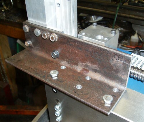
 We've skipped a few more steps here. These are all 1/4" capscrews, but some
are standard 7/16" head and some are oddball 3/8" head; they're actually small
block Chevy timing chain cover screws. You'll notice the two 3/8" screws at
the upper right; those are the two you saw earlier, attaching the adapter
plate. Note the two other 3/8" screws in the corner of the angle; I added two
more to hold the adapter to the angle.
We've skipped a few more steps here. These are all 1/4" capscrews, but some
are standard 7/16" head and some are oddball 3/8" head; they're actually small
block Chevy timing chain cover screws. You'll notice the two 3/8" screws at
the upper right; those are the two you saw earlier, attaching the adapter
plate. Note the two other 3/8" screws in the corner of the angle; I added two
more to hold the adapter to the angle.
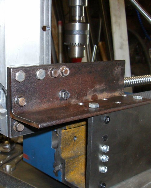
Down below the angle, you can see a 3/8" head screw going into the holes drilled and tapped into the motor bracket, and the two 7/16" screws along the top edge going into the holes we saw in the previous picture. Those screws go through clearance holes in the adapter plate.
That's four screws holding the adapter to the angle, and four more holding
the motor bracket.
 Same setup. different view.
KDNtool Z-axis doesn't block gibs, goes through center of head. No ballscrew option, though, and $190 for Acme!
The Hossmachine plans are similar to the KDNtool. The KDN ballscrew goes down, through the head casting, and the bottom is exposed to chips. The Hossmachine screw goes up above the machine. Unfortunately Hossmachine doesn't sell a Z kit, though the plans are free from hossmachine.info
The CNCFusion Z-axis kit blocks the gib screws. I can't imagine why they didn't move the screw forward a bit, or put it on the other side. Having to remove the Z drive to adjust the gibs is crazy. It is particularly inexplicable considering how nice their X and Y axis bits are.
The KDNTools Z-axis kit is $190 from LMS, and it's an Acme thread instead of a ballscrew. There was no ballscrew option I could find when I looked (June 2008). Even so, if I had it to do over again, I'd buy the CNCFusion XY kit and the KDNTool Z kit.
Syil OEM setup puts the ballscrew behind the column, wings reach around from the headstock to get to the ballnut.
Hossmachine Z mounts ballscrew solidly to head; ballnut captured by timing gear, spins with timing gear against thrust bearing
KDNtools mounts Acme nut inside head, turns Acme screw