Author: Dave Williams; dlwilliams=aristotle=net
The limited Y travel stopped me from buying an X2 for over a year, until I figured I could mount a rotary table on it to effectively double the travel. I still plan to do that, but here's how to bump the travel from 3.7 to 5.7 inches.
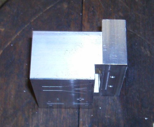
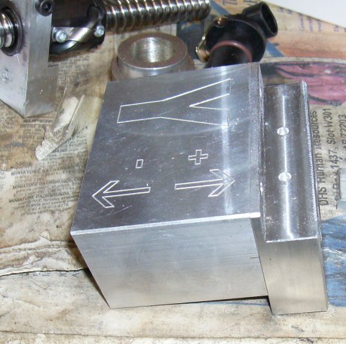 The CNCFusion Y motor mount is assembled from three pieces. There's a front
plate that mounts the motor, which isn't shown here, a piece of aluminum
channel in the middle, which is the part with the pretty Y direction diagram
routed into it, and the bearing block, which is the notched part on the right.
The CNCFusion Y motor mount is assembled from three pieces. There's a front
plate that mounts the motor, which isn't shown here, a piece of aluminum
channel in the middle, which is the part with the pretty Y direction diagram
routed into it, and the bearing block, which is the notched part on the right.
As delivered from CNCFusion the bearing block is just a block. It is attached to the channel with four socket head cap screws, and has two holes in the top to mount the X2's front way cover. You can see where these holes used to be.
Here, I milled the back of the bearing block away so the table could slide
.60" further forward.
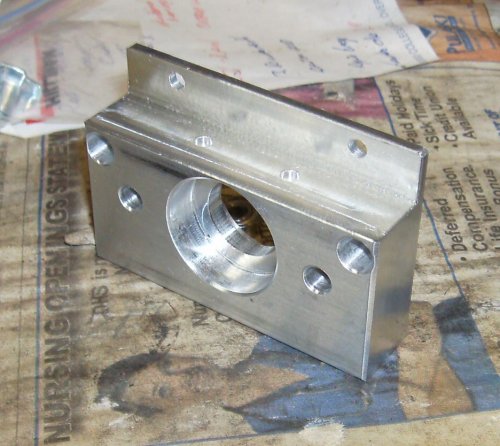 This is the back side of the block, that goes against the base casting of the
mill. The two large counterbored holes go forward into the channel, the two
smaller ones down lower come through from the other way to attach the block to
the base casting.
This is the back side of the block, that goes against the base casting of the
mill. The two large counterbored holes go forward into the channel, the two
smaller ones down lower come through from the other way to attach the block to
the base casting.
The original plan was to use countersunk screws to hold the top to the
channel. You can see the original holes there.
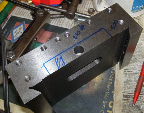 To get a little more travel, I decided to cut out the front of the saddle a
bit. There was plenty of metal there, so it wouldn't weaken anything.
To get a little more travel, I decided to cut out the front of the saddle a
bit. There was plenty of metal there, so it wouldn't weaken anything.
 Since I had milled the mounting block down to the top edges of the
counterbores, it stuck up a bit higher than the bottom of the table. I cut a
little clearance in the table so it would slide up over the block.
Since I had milled the mounting block down to the top edges of the
counterbores, it stuck up a bit higher than the bottom of the table. I cut a
little clearance in the table so it would slide up over the block.
 Further reflection showed this was all wankery. Leave the saddle alone, and
just cut the freakin' motor mount as required. I could have saved a lot of
time and trouble if I'd done it right the first time.
Further reflection showed this was all wankery. Leave the saddle alone, and
just cut the freakin' motor mount as required. I could have saved a lot of
time and trouble if I'd done it right the first time.
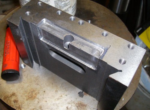
 After the cut. I went ahead and gave it a full inch of clearance even though
I'd already notched the saddle. in case I decided to replace the saddle later.
After the cut. I went ahead and gave it a full inch of clearance even though
I'd already notched the saddle. in case I decided to replace the saddle later.
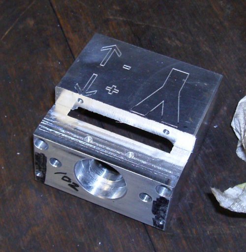 I should have cut down into the counterbores, and clipped the screws if
necessary, to get proper clearance for the saddle. The screws don't ever need
to come out, so you can carve right into them if you need to. Note the holes
I added for some additional screws down lower.
I should have cut down into the counterbores, and clipped the screws if
necessary, to get proper clearance for the saddle. The screws don't ever need
to come out, so you can carve right into them if you need to. Note the holes
I added for some additional screws down lower.
As much as these bits cost, I admit to a pang when I started carving on
them... the CNCFusion kit cost substantially more than the X2 itself did.
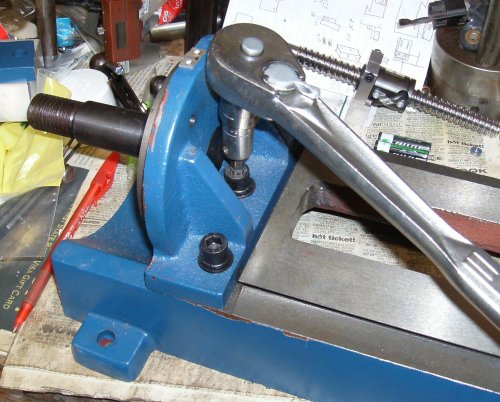 With the saddle moving forward an inch, I needed it to move back an inch,
too. The simplest way is to just move the column back an inch. Fortunately,
it's bolted to an angle bracket, which is in turn bolted to the base.
With the saddle moving forward an inch, I needed it to move back an inch,
too. The simplest way is to just move the column back an inch. Fortunately,
it's bolted to an angle bracket, which is in turn bolted to the base.
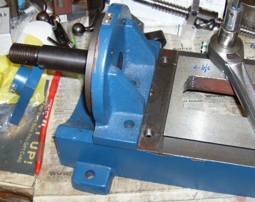 And there's my inch! Unfortunately the base is stepped down behind the
machined area, and there's no solid metal under there to tap into.
And there's my inch! Unfortunately the base is stepped down behind the
machined area, and there's no solid metal under there to tap into.
No problemo! I'll make an adapter plate.
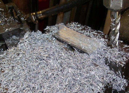
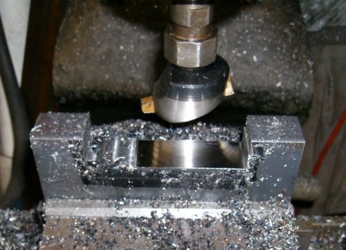 A piece of 1x3 hot rolled bar will form the adapter. It was faster to use
the flycutter than an end mill.
A piece of 1x3 hot rolled bar will form the adapter. It was faster to use
the flycutter than an end mill.