Author: Dave Williams; dlwilliams=aristotle=net
The other school says any CNC machine needs limit switches, period. Not being experienced enough to have an opinion one way or the other, but noticing the Mach documentation spent a lot of time on limit switches, I decided to add some. If nothing else, they'd provide convenient zeroing points for the axes.
Several of the guys on CNCzone had posted pictures of their X2 limit switches, which helped. I went a slightly different direction, of course.
Almost all small mills use "micro" or "cherry" switches. These are the small clicker-switches you can buy for a few dollars each from electronics supply companies. They're theoretically liquid-resistant, cheap, and small. If one craps out, you just solder another one on.
Real machine tool limit switches are absolutely reliable, precise, the size of a cellular phone, and cost $50-$100 each... on eBay. New ones are even more. So microswitches it was to be.
There are a number of conflicting design requirements for limit switches: they must be protected from coolant and chips, yet easily accessible for replacement; they must be accurately fixed, yet adjustable, the switches should be fixed and their triggers should move, so the wires don't flex, etc.
This is how I did mine. The X and Y switches are all mounted to the saddle, with one bundle of wires coming out to a breakout box. The table can be removed without disturbing the switches, and the saddle can be removed as an assembly with the switches and oil lines. The switches are fixed and have adjustable triggers.
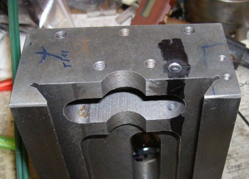
 I started with the X+ switch. The CNCFusion kit puts the X ballnut on the
right side of the table, with a thick spacer to move the outer ballscrew
support out. So when the table is all the way to the left, there's a gap
between the right side and the saddle.
I started with the X+ switch. The CNCFusion kit puts the X ballnut on the
right side of the table, with a thick spacer to move the outer ballscrew
support out. So when the table is all the way to the left, there's a gap
between the right side and the saddle.
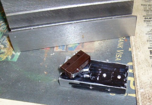
 I cut a block of scrap aluminum to make a mounting bracket. I mounted it
flush with the outside of the saddle.
I cut a block of scrap aluminum to make a mounting bracket. I mounted it
flush with the outside of the saddle.
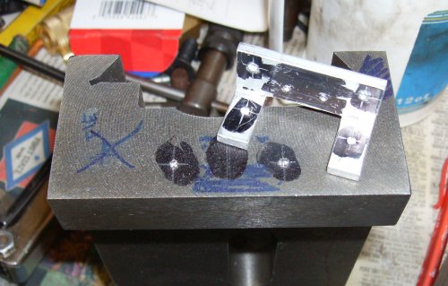
 No local supplier stocked any screws small enough to go through the holes in
the microswitches, so I tapped their bodies #4-40 UNC. Turns out that's how
most people wind up doing it.
No local supplier stocked any screws small enough to go through the holes in
the microswitches, so I tapped their bodies #4-40 UNC. Turns out that's how
most people wind up doing it.
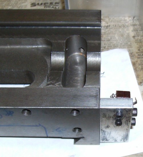
 There's room on the end plate to drill and tap for a screw to run over to the
switch. This lets me turn the screw to adjust the limit for X+.
There's room on the end plate to drill and tap for a screw to run over to the
switch. This lets me turn the screw to adjust the limit for X+.
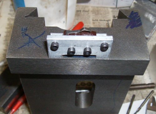
 I drilled a hole to run the limit switch wires through the saddle over to the
left side. There's another tapped hole partway through with a plastic wire
retainer to keep the wires from getting into the ballscrew.
I drilled a hole to run the limit switch wires through the saddle over to the
left side. There's another tapped hole partway through with a plastic wire
retainer to keep the wires from getting into the ballscrew.
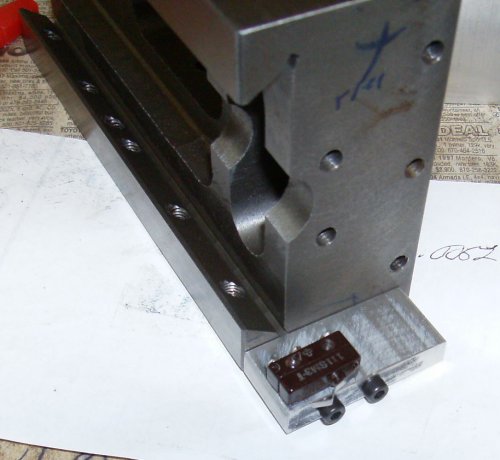
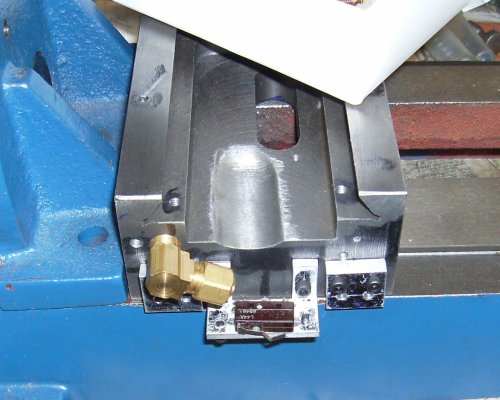
 Now for the X- limit switch. I cut a piece of 3/4" aluminum angle for the
bracket. Two #6-32 screws hold it to the saddle, two through-holes for
mounting the switch, and two #4-40 screws at the corners to mount a wire
brace.
Now for the X- limit switch. I cut a piece of 3/4" aluminum angle for the
bracket. Two #6-32 screws hold it to the saddle, two through-holes for
mounting the switch, and two #4-40 screws at the corners to mount a wire
brace.
 The slot behind the bracket is there so the wires can run behind the switch.
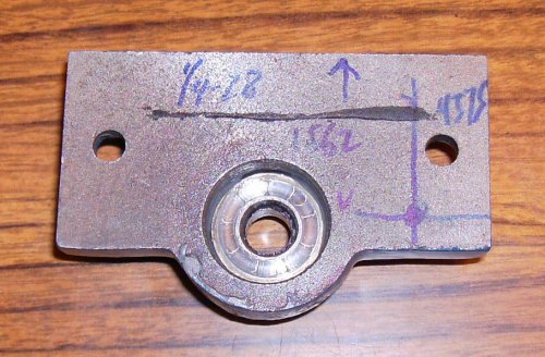
 Now with the Y+ and Y- switch brackets. Had I thought far enough ahead, I
could have made one bracket to hold all three switches.
Now with the Y+ and Y- switch brackets. Had I thought far enough ahead, I
could have made one bracket to hold all three switches.