Roll
Centers
Myths
and Reality
Version
4.00 of WinGeo3 computes Force-Based Roll Centers as well as the more familiar
Kinematic Roll center.
The Kinematic
Roll Center
The
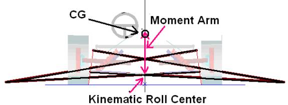
most familiar roll center is more properly known as the kinematic roll center. This is constructed by drawing lines from the
tire contact patch to the respective instant center. The kinematic roll center
is the intersection of these lines.
The
chassis can rotate about the Kinematic
Roll Center without moving the tire contact patches. This is a simple
consequence of kinematic theory. If the vehicle were parked this might be a
useful piece of information. But the vehicle is moving rapidly and probably, if
there are lateral forces, following a curved path and the racing tires are
certainly not rigid bodies. The kinematic roll center is of value in determining
the distribution of loads on the tire when the vehicle is subject to lateral
forces. With the kinematic roll center under the center of gravity, the moment
arm (the distance between the roll center and the CG) is very useful.
The
moment arm is the distance from the kinematic roll center to the center of
gravity, or CG. This distance specifies the overturning moment at each end of
the vehicle and thus the load transfer calculations. This is an important part
of vehicle dynamics.
Most
production cars are symmetric as are most road racing cars. But few oval track
racing vehicles are symmetric and other cars become asymmetric as soon as they
role in reaction to lateral cornering forces. Most vehicle dynamic text books
mention this in their discussion of roll centers, but few do more than mention
it. The distance from the kinematic roll center is not the relevant moment arm we need to determine load transfer.
The Asymmetric
Case
When
we deal with an asymmetric vehicle there are two moment arms; one for each tire.
The relevant moment arm is the distance from the CG down to the point on the
line connecting each tire contact patch to the respective instant center. If the
kinematic roll center is not under the CG then these points will be different.
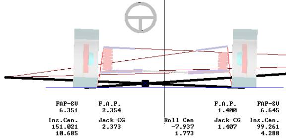
The
relevant points are the Jacking-CG values of 1.407 inches for the right tire and
2.373 for the left tire. The height of the kinematic roll center - 1.773 inches
- is of little interest.
Force-Based
Roll Center
The
kinematic construction described above is useful, but it is based only on the
A-arm links. It ignores the steering tie-rod. The Force-based Roll Centers
corrects this problem by incorporating all
of the links. The Force Application Points, or FAP, values are 1.400 for the
right side and 2.354 for the left. These are the most accurate values in
calculating load transfer.