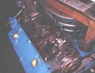
My brother Kevin is the current custodian of the family's '65 Chevy pickup. It's the heavy duty 3/4 ton long wheelbase model, with steel door panels, steel headliner, and a rubber mat on the floor - just hose it out. Two barrel 283, granny-low four speed, and a 4.56 Detroit Locker in the back. Our Dad bought it in 1970. Since then it's carried a cabover camper, then a camper shell, hauled concrete blocks, wet sand, trailers, and even a small mobile home.
After 35 years the 283 was getting a little tired. Kevin decided a whole new motor would be the way to go. The 283 actually had adequate power, even in its senior citizen years. Kevin considered building a fresh 283, or maybe moving to a 305. I had the basic parts on hand to do a 307. Dave's Law: "Cheap Is A Quality Overcoming Many Faults."
The 307 can be considered an underbored 327 or a stroked 283. It's an eighth of an inch more bore than a 305 and a quarter inch shorter stroke. By rights they should run pretty good - better than a 305 - but production 307s were all low compression, wimpy cam timing, generally low performance motors. Kevin's 307 is none of the above.
 Disassembling an old set of lifters to use as plugs for the lifter bores. I'm
partial to spraying white epoxy paint in the lifter valley. I could claim it
enhances oil drainback or something, but in truth, I just like the way it
looks. I have some nice plastic plugs I use for Ford motors, but the Chevy's
smaller diameter lifters required some fangling.
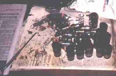
Disassembling an old set of lifters to use as plugs for the lifter bores. I'm
partial to spraying white epoxy paint in the lifter valley. I could claim it
enhances oil drainback or something, but in truth, I just like the way it
looks. I have some nice plastic plugs I use for Ford motors, but the Chevy's
smaller diameter lifters required some fangling.
 A bit of tape wrapped around the end of the lifter keeps it from falling
through. The block came out of the hot tank, was pressure washed, and then
thoroughly scrubbed with Tide and a bristle brush before being dried with
compressed air. It's trying to rust even as I'm shooting the picture. The
cleaner the metal is, the better the paint sticks.
A bit of tape wrapped around the end of the lifter keeps it from falling
through. The block came out of the hot tank, was pressure washed, and then
thoroughly scrubbed with Tide and a bristle brush before being dried with
compressed air. It's trying to rust even as I'm shooting the picture. The
cleaner the metal is, the better the paint sticks.
 Just came out of the honing tank. Now I get to run a tap in every single
threaded hole to make sure the threads are clean...
Just came out of the honing tank. Now I get to run a tap in every single
threaded hole to make sure the threads are clean...
 Cleaning the cylinder bores. I'm using Marvel Mystery Oil, which is just a
decent grade of 5-weight oil, but ordinary automatic transmission fluid works
just as well. The oil floats honing grit out of the cylinders where it can be
picked up by a paper towel. The cylinders are honed to a #400 finish, which
is pretty darned smooth. Even so, the first few passes of the paper towel
come out silver with metal. You keep oiling and wiping until the towels come
out clean. No, most shops *don't* do this; it's a pain in the ass, and time
is money.
Cleaning the cylinder bores. I'm using Marvel Mystery Oil, which is just a
decent grade of 5-weight oil, but ordinary automatic transmission fluid works
just as well. The oil floats honing grit out of the cylinders where it can be
picked up by a paper towel. The cylinders are honed to a #400 finish, which
is pretty darned smooth. Even so, the first few passes of the paper towel
come out silver with metal. You keep oiling and wiping until the towels come
out clean. No, most shops *don't* do this; it's a pain in the ass, and time
is money.
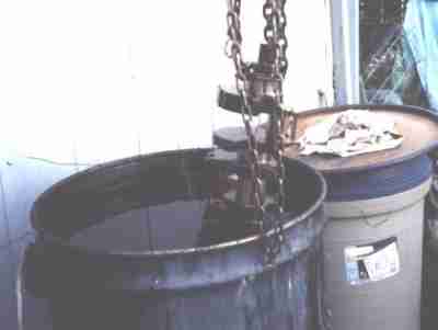 The 307 crank coming out of the hot caustic cleaning tank. I use a chain
hoist because straight-arming a 50 pound crank (at 180 Fahrenheit and covered
with caustic cleaner) is no fun. This is an ordinary cast crank, large
journal.
The 307 crank coming out of the hot caustic cleaning tank. I use a chain
hoist because straight-arming a 50 pound crank (at 180 Fahrenheit and covered
with caustic cleaner) is no fun. This is an ordinary cast crank, large
journal.
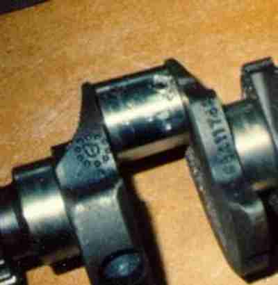 This particular crank had been damaged on the first rod throw.
Someone's backyard overhaul didn't include tightening the rod nuts, and one
cap had come off and the bolt had gouged the oil hole in the rod throw. I
dismembered an old 'D' cell flashlight battery, carved the carbon rod with a
pocket knife until it fit in the mangled oil hole, preheated the crank with a
large propane torch, and MIG-welded the damaged section. Then I tapped the
carbon plug out from the other end of the oil gallery; no need to drill
through a weld.
This particular crank had been damaged on the first rod throw.
Someone's backyard overhaul didn't include tightening the rod nuts, and one
cap had come off and the bolt had gouged the oil hole in the rod throw. I
dismembered an old 'D' cell flashlight battery, carved the carbon rod with a
pocket knife until it fit in the mangled oil hole, preheated the crank with a
large propane torch, and MIG-welded the damaged section. Then I tapped the
carbon plug out from the other end of the oil gallery; no need to drill
through a weld.
Now the crank is cosmetically pretty after being turned 10/10. You can
see where the metal is a slightly different color after the crank was
reground, but it's on-size. I don't have an "after" picture to show you.
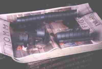 Rod and main bearings. They've been coated with Tech Line's TLML moly coat.
This is right after they've been sprayed; they get baked for several hours,
then polished afterward.
Rod and main bearings. They've been coated with Tech Line's TLML moly coat.
This is right after they've been sprayed; they get baked for several hours,
then polished afterward.
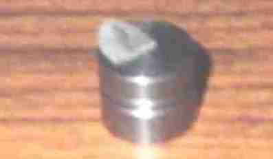
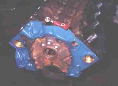 Putting the cup plugs in the front oil galleries. A special cup plug driver
is looking at you head-on; it's the round silver thing at the cap end of the
Loctite tube. Swab the holes out with acetone, wipe the plugs with acetone,
dab them with Loctite, drive the plugs in, then stake the holes with a large
chisel - notice the marks. Not that I'm paranoid or anything...
Putting the cup plugs in the front oil galleries. A special cup plug driver
is looking at you head-on; it's the round silver thing at the cap end of the
Loctite tube. Swab the holes out with acetone, wipe the plugs with acetone,
dab them with Loctite, drive the plugs in, then stake the holes with a large
chisel - notice the marks. Not that I'm paranoid or anything...
 The back plugs screw in. Getting the old ones out required an oxyacetylene
torch, a BFH, and for one particularly stubborn plug, a drill and a 1/4 NPT
tap to repair the threads. I'm installing new plugs with Teflon tape. The
next guy who needs to remove the plugs will be able to just unscrew them with
an Allen wrench.
The back plugs screw in. Getting the old ones out required an oxyacetylene
torch, a BFH, and for one particularly stubborn plug, a drill and a 1/4 NPT
tap to repair the threads. I'm installing new plugs with Teflon tape. The
next guy who needs to remove the plugs will be able to just unscrew them with
an Allen wrench.
 Removing the old cam sprocket from the crank. It doesn't matter when you do
this step, but it's easiest when the crank is supported in a block. The strip
of wood on the right keeps the crank from turning.
Removing the old cam sprocket from the crank. It doesn't matter when you do
this step, but it's easiest when the crank is supported in a block. The strip
of wood on the right keeps the crank from turning.
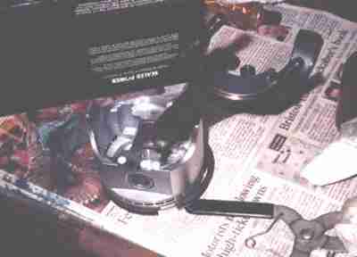 The pistons and rods have been assembled, the rings are installed, and the rod
bearing just went in. Now it gets two stroke oil on the rings, Mobil 1
synthetic oil on the wristpin and the skirts, and a special bearing lube on
the bearing and the sides of the rod where it rubs the crank cheek and the
other rod. A special lubricant for every occasion... lots of people use plain
old motor oil for everything, which works okay too.
The pistons and rods have been assembled, the rings are installed, and the rod
bearing just went in. Now it gets two stroke oil on the rings, Mobil 1
synthetic oil on the wristpin and the skirts, and a special bearing lube on
the bearing and the sides of the rod where it rubs the crank cheek and the
other rod. A special lubricant for every occasion... lots of people use plain
old motor oil for everything, which works okay too.
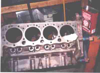
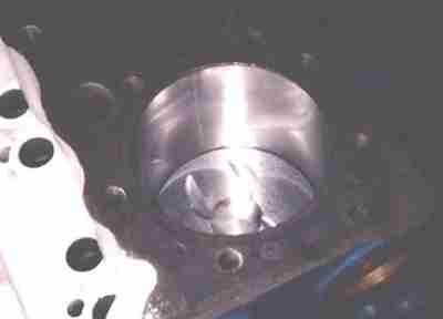 Here's an installed piston at bottom dead center. Notice the smooth cylinder
wall finish. Speed Pro, who made the rings, calls for a very smooth finish
for moly rings. Yes, they'll seat just fine. The days of crosshatched
cylinder walls went away with chrome rings. Notice these are flat top pistons
instead of regular 307 dish tops. With the 305 heads we'll be getting over
9:1 CR.
Here's an installed piston at bottom dead center. Notice the smooth cylinder
wall finish. Speed Pro, who made the rings, calls for a very smooth finish
for moly rings. Yes, they'll seat just fine. The days of crosshatched
cylinder walls went away with chrome rings. Notice these are flat top pistons
instead of regular 307 dish tops. With the 305 heads we'll be getting over
9:1 CR.
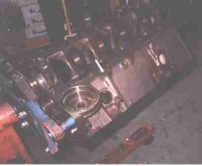
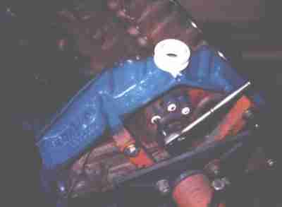
 I'm fitting the crank scraper here. They're a sort of universal fit for a
350, but it still required trimming for a 307. Fortunately a Dremel tool made
it a short job. The scraper gets glued to the block with silicone sealer and
the oil pan gasket goes over it. Also in view are the Milodon oil pump
stud, Teflon tape on the water drain plug, brass freeze plugs, and my nifty
crank turning socket.
I'm fitting the crank scraper here. They're a sort of universal fit for a
350, but it still required trimming for a 307. Fortunately a Dremel tool made
it a short job. The scraper gets glued to the block with silicone sealer and
the oil pan gasket goes over it. Also in view are the Milodon oil pump
stud, Teflon tape on the water drain plug, brass freeze plugs, and my nifty
crank turning socket.
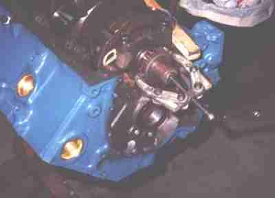
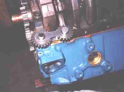 Now I'm fitting the Pete Jackson gear drive. The idler dogbone axles extend
back to hit the front of the block. They are made extra-long since the blocks
are just castings in front, and vary in their shape. I used a belt sander to
shorten the axles a little at a time.
Now I'm fitting the Pete Jackson gear drive. The idler dogbone axles extend
back to hit the front of the block. They are made extra-long since the blocks
are just castings in front, and vary in their shape. I used a belt sander to
shorten the axles a little at a time.
 You install the dogbone with clay, tighten the timing chain cover (with a
gasket), disassemble, and measure the thickness of the clay. We're right in
spec.
You install the dogbone with clay, tighten the timing chain cover (with a
gasket), disassemble, and measure the thickness of the clay. We're right in
spec.
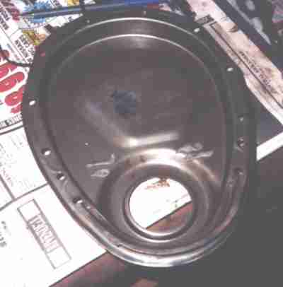 The inside of the timing chain cover, showing more checking clay. Grinder
marks are where the timing chain tab used to be welded on front; removing it
left holes that had to be welded shut.
The inside of the timing chain cover, showing more checking clay. Grinder
marks are where the timing chain tab used to be welded on front; removing it
left holes that had to be welded shut.
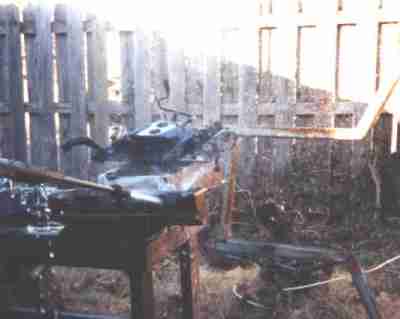
 Here it is, all ready to go.
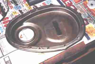 The steel strip welded in the cover provides a little extra support for the
camshaft thrust bumper. Nothing much holds a Chevy cam in place when it's
running - lifter thrust does some, but most of it is tension on the chain.
With gears instead of a chain, the cam has a tendency to walk forward. The
Pete Jackson gear drive came with a ball bearing thrust bumper.
The steel strip welded in the cover provides a little extra support for the
camshaft thrust bumper. Nothing much holds a Chevy cam in place when it's
running - lifter thrust does some, but most of it is tension on the chain.
With gears instead of a chain, the cam has a tendency to walk forward. The
Pete Jackson gear drive came with a ball bearing thrust bumper.
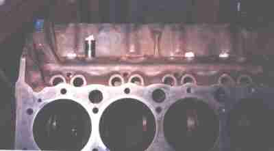
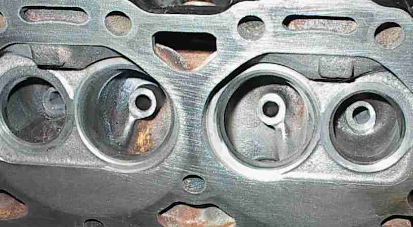
 We topped the block with a pair of late model 305 heads. These are actually
350 heads, but they're very similar to the 305 heads. The intake port is very
tall and has a "corkscrew" vane that causes the incoming air to swirl.
Shooting water through the port with a garden hose makes a nice wide fan. The
swirl reduces emissions some, but its major benefit is fuel economy. For very
similar heads on the 4.3 V6, Chevrolet claimed figures on the order of an 8%
drop in power over 3000 RPM with a 12% increase in fuel economy and torque
across the entire useable powerband. This was a no-brainer for the 307; we
have power to burn compared to the 283, and the mileage and crisp throttle
response would be very nice. Note the sharp edge just below the intake valve
seat. This is a "fuel tripper" designed to re-introduce liquid fuel running
along the port floor into the airstream. According to David Vizard, who is
knowledgeable about such things, smoothing out the bowl area would give a
small increase in power with the penalty of a loss of fuel economy. We left
the fuel trippers alone for this particular application.
We topped the block with a pair of late model 305 heads. These are actually
350 heads, but they're very similar to the 305 heads. The intake port is very
tall and has a "corkscrew" vane that causes the incoming air to swirl.
Shooting water through the port with a garden hose makes a nice wide fan. The
swirl reduces emissions some, but its major benefit is fuel economy. For very
similar heads on the 4.3 V6, Chevrolet claimed figures on the order of an 8%
drop in power over 3000 RPM with a 12% increase in fuel economy and torque
across the entire useable powerband. This was a no-brainer for the 307; we
have power to burn compared to the 283, and the mileage and crisp throttle
response would be very nice. Note the sharp edge just below the intake valve
seat. This is a "fuel tripper" designed to re-introduce liquid fuel running
along the port floor into the airstream. According to David Vizard, who is
knowledgeable about such things, smoothing out the bowl area would give a
small increase in power with the penalty of a loss of fuel economy. We left
the fuel trippers alone for this particular application.
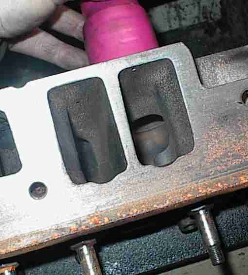
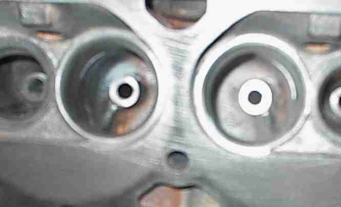
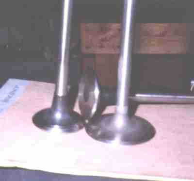
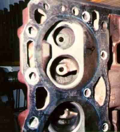 Here's another view of the intake port. Also notice the relocated spark plug,
up high and pushed closer to the center of the chamber. Kevin's heads have
had the valves unshrouded all the way to the cylinder walls, a fancy three
angle valve job, very minor porting on the exhaust side, and modified valves
with a 20 degree back-cut for better airflow. Plus they're cut for 7/16"
screw in studs and guide plates.
Here's another view of the intake port. Also notice the relocated spark plug,
up high and pushed closer to the center of the chamber. Kevin's heads have
had the valves unshrouded all the way to the cylinder walls, a fancy three
angle valve job, very minor porting on the exhaust side, and modified valves
with a 20 degree back-cut for better airflow. Plus they're cut for 7/16"
screw in studs and guide plates.
DISPLACEMENT -------------------------------------------------------------

3.905 bore   (+.030)
3.250 stroke (+.250)
311 CID, 5103cc (5.1 L)


COMPONENTS ---------------------------------------------------------------

crankshaft:
        Chevy 307, cast
        mains -.010
        rods -.010
        balanced
        bearings .010, Clevite 77
        minor weld repairs on #1 and #2 throws
        polished journals

pistons:
        Sterling/Federal Mogul
        cast 307 Chevy, .030 over
        flat top with four reliefs

rings:
        standard small block Chevy. 3.875 +.030, Speed-Pro
        side clearance .003 top and second
        ring gaps .011 top, .011 second, .015 oil

rods:
        5.7" large journal
        TLML moly coated bearings .010, Clevite 77
        rod side clearances .012
        resized big ends (minimum size)

block:
        307, two bolt, two piece rear main
        bored .030
        honed to .003 piston/wall clearance
        2 piece rear main seal (red silicone around edges)
        new core plugs (red silicone sealer)
        new cam bearings  (Clevite 77)
        all threaded holes chased

timing set:
        Pete Jackson dual idler gear drive
        cam installed at 4 advanced

cam:
        Iskenderian hydraulic 270 Mega #201271
        221/221 @.050, .465/.465 lift (w/1.5 rockers) .511/.511 (1.6)  108 LC
        Rhoads variable-duration hydraulic lifters

oiling:
        new Milodon high volume, high pressure pump
        new Milodon oil pump pickup
        Milodon crank wiper, trimmed to fit, glued in place with Ultra Copper
        Milodon steel pump to drive rod bushing
        stock Chevy oil pump drive rod
        Milodon oil pump mounting stud
        new Summit oil pan

intake:
        Offenhauser Dual Port 360, Holley pattern

carburetor:
        Carted 625 AFB, CFM

ignition:
        Chevy HEI

heads:
        187 casting, '90s 305 "corkscrew port" high swirl
        late model re-angled center intake manifold bolts
        for center-bolt valve covers
        1.84/1.50 valves (original size)
        45 degree valves and seats
        new bronze guide liners
        .001 valve/guide clearance
        intake valve stem seals - shields, O-rings and umbrellas
        exhaust valve stem seals - shields and O-rings
        Competition Products #2350 valve springs, 120# @ 1.700, 300# @ 1.250
        1.750 installed height
        standard height intake keepers, -.050 exhaust keepers
        bosses cut down and tapped for screw-in studs
        ARP 134-7103 7/16" screw-in studs, torqued to 55 ft-lb with sealer
        Crane 11650-1 stepped guide plates
        Crane 11747-16 7/16", 1.6 ratio cast aluminum full roller rockers
        surfaced flat on deck and intake face
        Magnafluxed
        valve seal vacuum checked

    porting:
        intake valves were back cut from the factory
        ditch cut faces

        exhaust valves 20 deg back cut, 45 deg chamfered on face

        sides of combustion chambers opened up to 3.905" bore size, plunge
          cut with seat grinding stones

        side cuts rolled into front of chamber with die grinder, outer edge
          extended to 3.905" bore size

        intake valve pocket quench side rolled back with die grinder

        intake and exhaust valve seats opened up to match OD of valve

        60-45-30 degree three angle valve job

        exhaust valve pockets cleaned up with die grinder

    notes:
        The intake ports were left alone, other than the larger diameter
        seats.  According to GM the sharp edges in the bowl are for fuel
        shear, to reintroduce fuel droplets into the airstream.  Most of the
        work was done in the combustion chambers, unshrouding the valves as
        per David Vizard's Chevrolet head porting book.  The 187 heads have
        the late model relocated spark plug, which is moved closer to the
        center of the chamber and slightly to the exhaust side.

===========================================================================
Yep, that's a fairly large cam for a small motor. We never got around to
CC'ing the chambers, but I expect the compression ratio to be around 9.5:1.
The truck is turning around 3500 RPM at freeway speed; there was no reason to
build an RV-type lug-around motor; instead, we built the engine to perform
best at cruise speed.
At the time this was written, the 307 was wrapped up on Kevin's enclosed back
porch while he was upgrading the transmission and rear end. The 283 still has
some life in it, and there's no sense in putting the new engine in until the
rest of the driveline is fixed. The truck has a 4.56 Detroit Locker and a
Borg/Warner T-5 five speed now, and the next thing on the list is a new
exhaust system for the new shorty headers. The 283 doesn't show any signs of
impending doom yet...