Author: Dave Williams; dlwilliams=aristotle=net
This engine is for Jay's 1975 Chevy van. He retrofitted it with a New Process four speed overdrive and floor shift. He normally uses it for hauling his model airplanes; when he gets the new engine in he'll use it to tow his Corvette to track events.
Jay had a case of first-engine-itis, so he put a lot more into the engine than he really needed. Instead of a stock 350, he wanted a .060-over 400 with 5.7 rods, coated everything, Vortec heads, retrofit hydraulic roller cam, that nifty Iskenderian two-gear cam drive, and various other odds and ends. Fine with me. [grin]
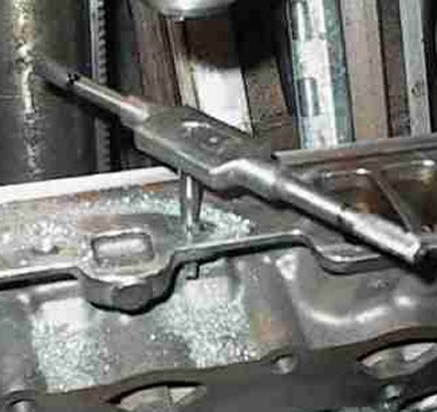
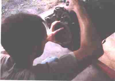 That's Jay setting up the gear drive to degree the cam and check rod/cam
clearance. Four rods had to be notched on the shoulders for cam clearance
even with a -.050 base circle cam.
That's Jay setting up the gear drive to degree the cam and check rod/cam
clearance. Four rods had to be notched on the shoulders for cam clearance
even with a -.050 base circle cam.
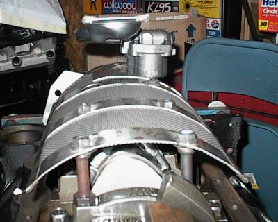
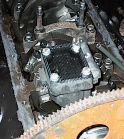
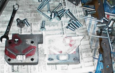
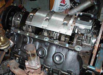
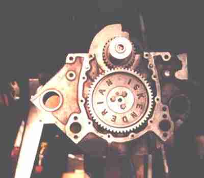 Here's the two-gear cam drive in all its glory. This was the very last
helical-cut pair Iskenderian had. I sandblasted them and coated them with
Tech Line TLML moly. The back of the cam gear has been cut to accept a flat
Torrington needle nearing to take cam thrust. A ball bearing thrust bumper
went on the nose when the timing cover was installed.
Here's the two-gear cam drive in all its glory. This was the very last
helical-cut pair Iskenderian had. I sandblasted them and coated them with
Tech Line TLML moly. The back of the cam gear has been cut to accept a flat
Torrington needle nearing to take cam thrust. A ball bearing thrust bumper
went on the nose when the timing cover was installed.
On a regular Chevy cam the lifters are offset and the lobes are crowned to pull the cam back into the block as it rotates. The back of the cam gear runs against the block. Not high tech, but it works.
Roller cams have no taper on the lobes, so they'll walk front to back unless you have some sort of thrust bumper.
You can still hear the gear drive whirring underneath the timing cover, but
it's not the scream of a straight cut racing three-gear setup.
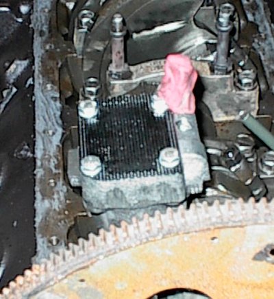
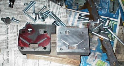
 I epoxied a piece of stainless steel to the inside of the timing cover for the
cam bumper to rub against. Right here, I'm using clay and a piece of plastic
film to check the clearance between the thrust bumper and the plate.
I epoxied a piece of stainless steel to the inside of the timing cover for the
cam bumper to rub against. Right here, I'm using clay and a piece of plastic
film to check the clearance between the thrust bumper and the plate.
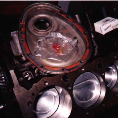
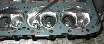
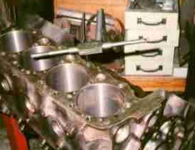
In this shot you can see the ceramic-coated piston domes and the smooth hone
of the cylinder bores. The engine has Total Seal gapless rings, which call
for a near mirror finish.
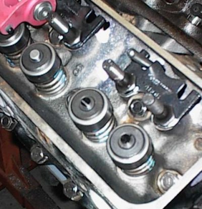
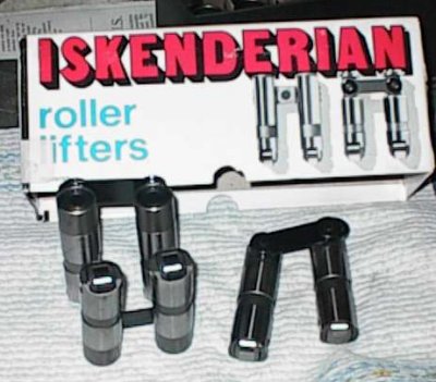 Iskenderian hydraulic retrofit roller lifters. These predate GM's adoption of
hydraulic rollers by a long time - they were in my 1975 catalog! Bring lots
of money; these suckers aren't cheap.
Iskenderian hydraulic retrofit roller lifters. These predate GM's adoption of
hydraulic rollers by a long time - they were in my 1975 catalog! Bring lots
of money; these suckers aren't cheap.
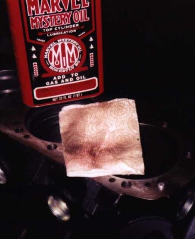
 Magic Marker ink is just fine for checking the pushrod length. When it's
correct, the wiped mark from the roller is in the middle of the valve stem.
Note the intake valve mark is off to the outside; this is actually in the
useable range, though not desirable if you have a choice.
Magic Marker ink is just fine for checking the pushrod length. When it's
correct, the wiped mark from the roller is in the middle of the valve stem.
Note the intake valve mark is off to the outside; this is actually in the
useable range, though not desirable if you have a choice.
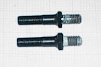
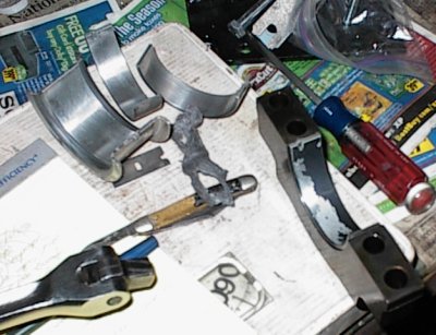
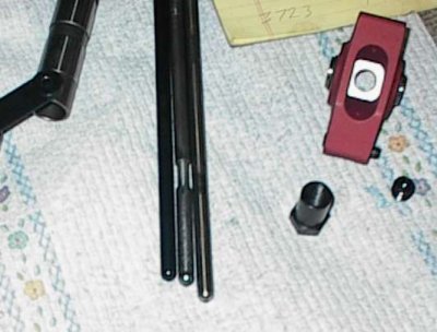 The pushrods Isky provided, which were supposed to work, were too short. One
of those is on the left. A stock flat tappet Chevy pushrod is on the right.
Hydraulic roller pushrods wouldn't work either. The adjustable pushrod in the
middle is what it took to get the wipe right.
The pushrods Isky provided, which were supposed to work, were too short. One
of those is on the left. A stock flat tappet Chevy pushrod is on the right.
Hydraulic roller pushrods wouldn't work either. The adjustable pushrod in the
middle is what it took to get the wipe right.
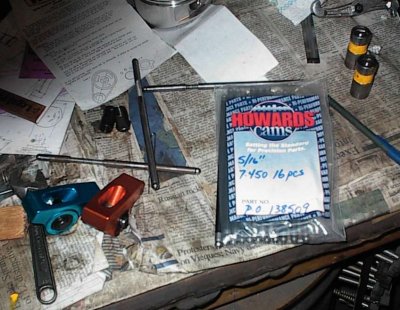 And here we are a couple of weeks later, with a brand new, custom-made set of
hardened 5/16" pushrods. The Isky lifters are an odd length, and no standard
pushrod will work.
And here we are a couple of weeks later, with a brand new, custom-made set of
hardened 5/16" pushrods. The Isky lifters are an odd length, and no standard
pushrod will work.
Yellow lifters are homemade checking tools, with solid internals shimmed down
.030" below the snap rings to simulate the height of hydraulic lifters when
they're correctly adjusted for preload.
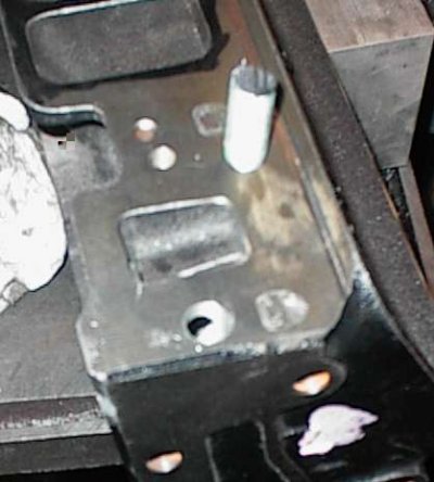
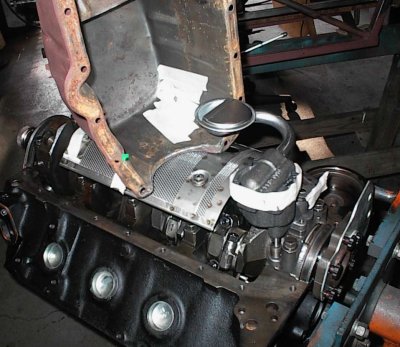
 This is the special distributor gear for the reverse-rotation cam. It's cast
iron to match up with the cast iron gear on the cam. The distributor and oil
pump turn the correct direction.
This is the special distributor gear for the reverse-rotation cam. It's cast
iron to match up with the cast iron gear on the cam. The distributor and oil
pump turn the correct direction.
In this rather blurry shot, the gear has just been sandblasted and will be
coated soon.
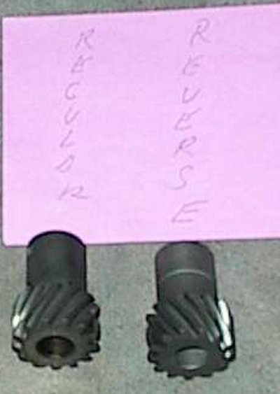 The Isky reverse rotation gear and the stock Chevy gear. We had to wait
several months for Isky to make another run of iron gears; normally all they
sell are bronze ones. But bronze ones wear and put particles in the oil, and
we wanted to avoid that.
The Isky reverse rotation gear and the stock Chevy gear. We had to wait
several months for Isky to make another run of iron gears; normally all they
sell are bronze ones. But bronze ones wear and put particles in the oil, and
we wanted to avoid that.
 Plain old HEI. I'm driving out the roll pin to remove the gear.
 The stock gear thrusts up, with a thrust washer on the bottom of the
distributor housing controlling end play. The reverse rotation gear thrusts
down, with the driving oil pump gear and the oil pump cover holding it. I
welded and ground on the end of the distributor shaft to extend it until it
just barely didn't sit down on the intake. Then I used shims under the
distributor to set the end play.
The stock gear thrusts up, with a thrust washer on the bottom of the
distributor housing controlling end play. The reverse rotation gear thrusts
down, with the driving oil pump gear and the oil pump cover holding it. I
welded and ground on the end of the distributor shaft to extend it until it
just barely didn't sit down on the intake. Then I used shims under the
distributor to set the end play.
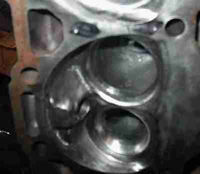
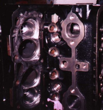
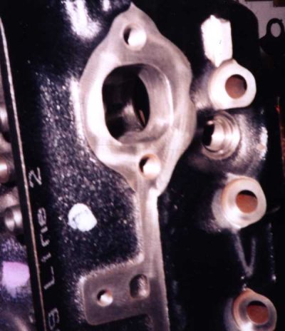
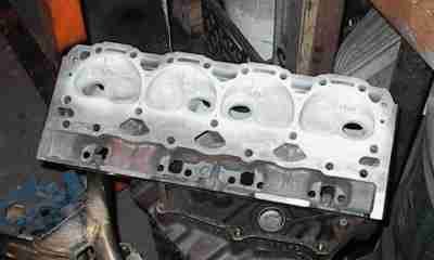
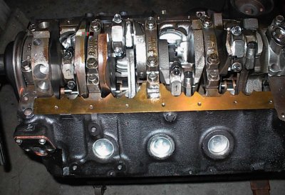
 The 400's siamesed block has extra water holes, called steam holes, to bleed
air pockets out of the areas where air bubbles would collect. The Vortec
heads don't have the holes. Here, I have located the 400 gasket with a couple
of dowels and am getting ready to center punch the head using the gasket to
locate the holes.
The 400's siamesed block has extra water holes, called steam holes, to bleed
air pockets out of the areas where air bubbles would collect. The Vortec
heads don't have the holes. Here, I have located the 400 gasket with a couple
of dowels and am getting ready to center punch the head using the gasket to
locate the holes.
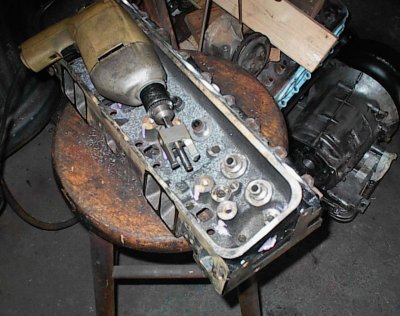
 Here are the center punches. Now on to the drill press...
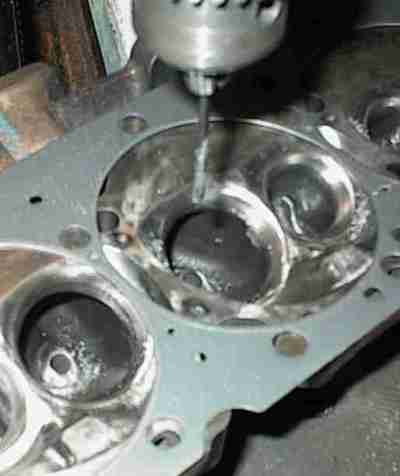 The bottom row of holes is straight, the top row has to be angled to clear an
adjacent head bolt boss. Factory Chevy 400 heads have two different sizes of
holes, both larger than what the gasket holes are. I drilled these to the
gasket size.
The bottom row of holes is straight, the top row has to be angled to clear an
adjacent head bolt boss. Factory Chevy 400 heads have two different sizes of
holes, both larger than what the gasket holes are. I drilled these to the
gasket size.
 A blurry shot of some 5/16" all-thread rod I sawed up for plugging the Vortec
intake bolt holes. At first it looked like a few of the holes would have to
be plugged because the new (old bolt pattern) holes would intersect, but it
turned out it wasn't necessary. I slotted the heads with a hacksaw, torqued
them in place with epoxy, and faced them off with the angle grinder. It
turned out I could have left all the 5/16" Vortec holes alone, but I didn't
realize that at the time.
A blurry shot of some 5/16" all-thread rod I sawed up for plugging the Vortec
intake bolt holes. At first it looked like a few of the holes would have to
be plugged because the new (old bolt pattern) holes would intersect, but it
turned out it wasn't necessary. I slotted the heads with a hacksaw, torqued
them in place with epoxy, and faced them off with the angle grinder. It
turned out I could have left all the 5/16" Vortec holes alone, but I didn't
realize that at the time.
 Center punching the new bolt holes. The Vortec head is very thin where the
bolt holes go. I decided to use 5/16-18 bolts to get more thread in the thin
sections instead of the usual 3/8-16. The Vortec only used four 5/16 bolts; I
figured six 5/16 bolts would be okay.
Center punching the new bolt holes. The Vortec head is very thin where the
bolt holes go. I decided to use 5/16-18 bolts to get more thread in the thin
sections instead of the usual 3/8-16. The Vortec only used four 5/16 bolts; I
figured six 5/16 bolts would be okay.
The Vortec intake ports are slightly taller than the old-style ports. It's
not a problem with most intakes. In this case, the exotic Algon IR intake Jay
has is already ground out for tall ports.
 Drill, countersink, tap. The middle holes were okay; the ones on the very
ends of the heads turned out to be a problem. The casting is very thin there,
then an air gap, then a large boss for an accessory hole is in there. The
drill rides down the side of the boss and elongates the hole. To drill the
hole straight you need some sort of grill guide.
Drill, countersink, tap. The middle holes were okay; the ones on the very
ends of the heads turned out to be a problem. The casting is very thin there,
then an air gap, then a large boss for an accessory hole is in there. The
drill rides down the side of the boss and elongates the hole. To drill the
hole straight you need some sort of grill guide.
 The manifold faces are very thin. At the ends, there are rounded accessory
hole bosses underneath. On one head, the drill wandered enough when it hit
the boss to throw the hole alignment off. So I drilled a much larger hole,
tapped, and installed a large plug of threaded rod.
The manifold faces are very thin. At the ends, there are rounded accessory
hole bosses underneath. On one head, the drill wandered enough when it hit
the boss to throw the hole alignment off. So I drilled a much larger hole,
tapped, and installed a large plug of threaded rod.
 The threaded rod was epoxied into place, drilled and tapped for the manifold
bolt, and then filed flush.
The threaded rod was epoxied into place, drilled and tapped for the manifold
bolt, and then filed flush.
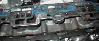
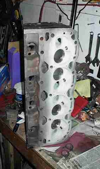
 Jay did some minor port work and polished the combustion chambers and exhaust
ports. The idea was to reduce area for heat transfer. Lots of work involved
here.
Jay did some minor port work and polished the combustion chambers and exhaust
ports. The idea was to reduce area for heat transfer. Lots of work involved
here.
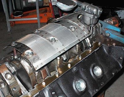
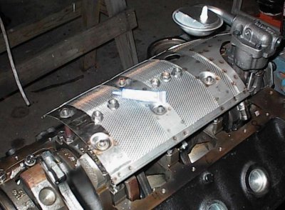
 We're coating the
heads with a ceramic thermal barrier, so they have to be sandblasted for the
coating to get a bite on the surface. It seemed a shame to sandblast Jay's
pretty polishing work...
We're coating the
heads with a ceramic thermal barrier, so they have to be sandblasted for the
coating to get a bite on the surface. It seemed a shame to sandblast Jay's
pretty polishing work...
Junk valves protect the intake seats; old spark plugs keep the threads from
getting messed up.
 Here's a nicely polished exhaust port...
 ...and here it is after sandblasting.
 Setting up to coat, scrubbed clean and washed with acetone to make sure there
are no silica particles or grease spots, ready to spray the ceramic coating.
Setting up to coat, scrubbed clean and washed with acetone to make sure there
are no silica particles or grease spots, ready to spray the ceramic coating.
Exhaust seats have been sandblasted; later, I'll cut through the ceramic with
the seat grinder to make a new seat.
 Freshly coated head. I laid the airbrush down and picked up the camera; the
coating is still wet.
Freshly coated head. I laid the airbrush down and picked up the camera; the
coating is still wet.
Getting even coverage in the exhaust ports without overdoing it and making the
stuff run can be a real bastard. I was lucky this time; the CBC2 sometimes
has a tendency to run or orange peel; this time it went on just fine.
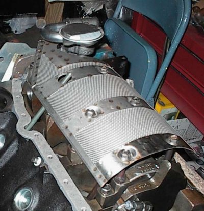
 Here we are prior to baking. It won't look any different after that, but the
coating will be rock hard.
Here we are prior to baking. It won't look any different after that, but the
coating will be rock hard.
The heads will get another pass over the belt surfacer to remove the overspray
coating. It's a lot easier to do that than to try to mask circular cutouts
with tape. The quench area runs much cooler than the rest of the chamber, so
it's not all that beneficial to coat it, and saves a lot of hassle if you
don't worry about it.
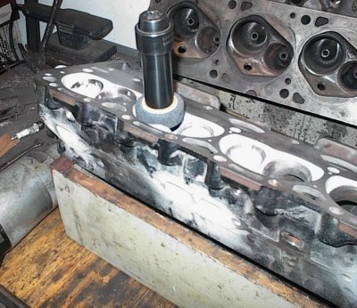 Grinding the new valve seats. The heads are almost done now.
 When I started to assemble the heads I found the Vortec guide bosses were too
large in diameter for the Isky springs, which have a flat internal damper,
like most small block Chevy springs. The Vortec uses single springs with no
damper. So I used a special carbide cutter on a drill to reduce the diameter
of the valve guides as well as shortening them a bit for extra seal to
retainer clearance.
When I started to assemble the heads I found the Vortec guide bosses were too
large in diameter for the Isky springs, which have a flat internal damper,
like most small block Chevy springs. The Vortec uses single springs with no
damper. So I used a special carbide cutter on a drill to reduce the diameter
of the valve guides as well as shortening them a bit for extra seal to
retainer clearance.
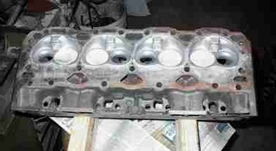
 And here we are, ground, faces resurfaced, cleaned, and ready to assemble.
Humid Arkansas weather means the machined surfaces start to rust as soon as
you blow them dry. Wiping them with light oil gets most of the rust off,
though you have to clean the oil off with acetone before assembling or the
gaskets won't stick right.
And here we are, ground, faces resurfaced, cleaned, and ready to assemble.
Humid Arkansas weather means the machined surfaces start to rust as soon as
you blow them dry. Wiping them with light oil gets most of the rust off,
though you have to clean the oil off with acetone before assembling or the
gaskets won't stick right.
 During final assembly I found out the rockers were bottoming out on the studs.
It turned out that the Vortec stud bosses are taller than the old-style stud
bosses, and the usual .230" cut for screw in studs needs to be more like
.330". The heads were already torqued down on the block, so rather than
destroy $60 worth of Victor graphite gaskets, I pulled the studs and cut down
the hexes on the lathe. Next time I'll know to cut the bosses deeper. All in
all, the Vortec heads turned out to be a major "learning experience."
During final assembly I found out the rockers were bottoming out on the studs.
It turned out that the Vortec stud bosses are taller than the old-style stud
bosses, and the usual .230" cut for screw in studs needs to be more like
.330". The heads were already torqued down on the block, so rather than
destroy $60 worth of Victor graphite gaskets, I pulled the studs and cut down
the hexes on the lathe. Next time I'll know to cut the bosses deeper. All in
all, the Vortec heads turned out to be a major "learning experience."
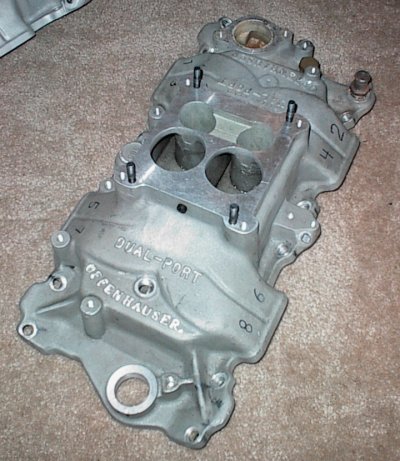
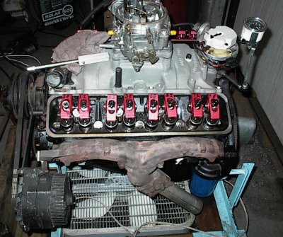
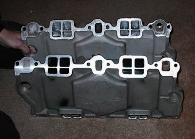 The Offenhauser Dual-Port is an excellent manifold for fuel economy and low
end torque, with okay, but not exceptional high-RPM power. Just the ticket
for a tow van. We had two manifolds to choose from; one brand new, but port
matched on the top runners, the other used, but stock.
The Offenhauser Dual-Port is an excellent manifold for fuel economy and low
end torque, with okay, but not exceptional high-RPM power. Just the ticket
for a tow van. We had two manifolds to choose from; one brand new, but port
matched on the top runners, the other used, but stock.
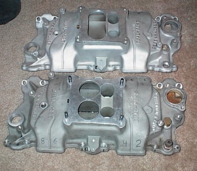 The new intake is on the top. The secondary plenum is open. The older intake
is on the bottom; the secondary intake is divided. Offy's "360" concept calls
for a divided intake. Apparently they discovered an open plenum worked better
for a Quadrajet pattern; the Holley intakes we looked at were all divided.
The new intake is on the top. The secondary plenum is open. The older intake
is on the bottom; the secondary intake is divided. Offy's "360" concept calls
for a divided intake. Apparently they discovered an open plenum worked better
for a Quadrajet pattern; the Holley intakes we looked at were all divided.
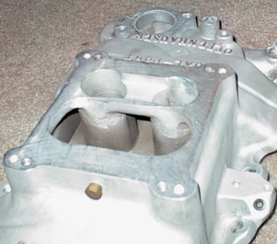
 The divider is visible here.
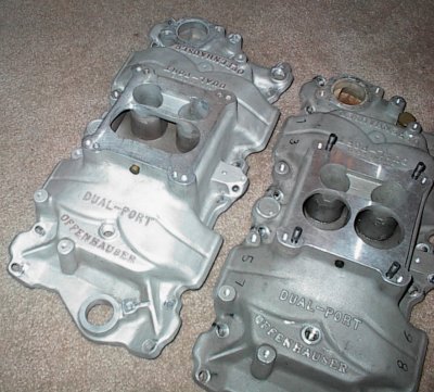 A comparison shot, though it'd hard to see the divider.
 The late, open plenum intake.
 The early, divided intake. Jay used the late intake.
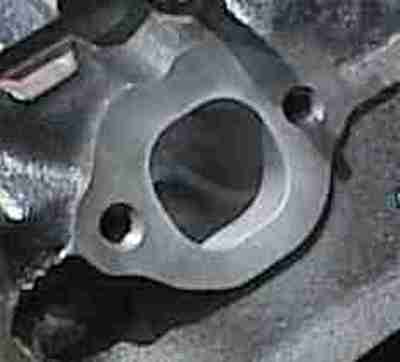
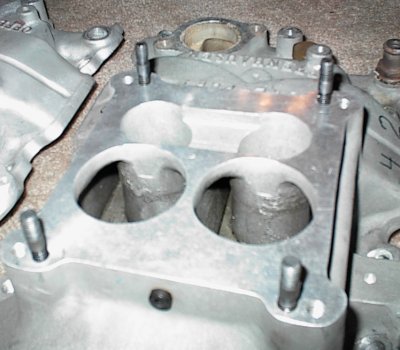
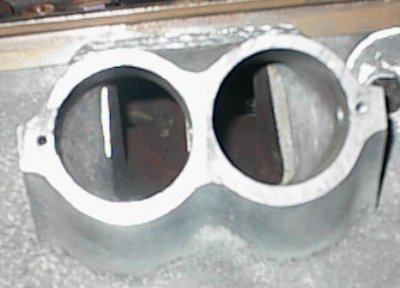 Port mismatch between the ported 283 intake and the Vortec heads. The intake
was actually not all that wide; it was matched to a standard Fel-Pro rebuilder
gasket. The Vortec bits are quite a bit narrower than that, though. And the
Vortec ports are about a quarter of an inch taller; there's just barely enough
gasket to seal.
Port mismatch between the ported 283 intake and the Vortec heads. The intake
was actually not all that wide; it was matched to a standard Fel-Pro rebuilder
gasket. The Vortec bits are quite a bit narrower than that, though. And the
Vortec ports are about a quarter of an inch taller; there's just barely enough
gasket to seal.
Some previous owner had welded extensions to the top of the manifold; it's a
good thing, too!
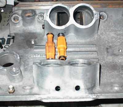 Ford "pencil" injectors from a Triton V10 are narrow enough to pair in the
center of the intake to shoot straight down the ports. Unfortunately, there's
no room to run fuel rails if you do that. I'm going to have to install the
injectors in the usual straight-down orientation.
Ford "pencil" injectors from a Triton V10 are narrow enough to pair in the
center of the intake to shoot straight down the ports. Unfortunately, there's
no room to run fuel rails if you do that. I'm going to have to install the
injectors in the usual straight-down orientation.
 Stainless steel screen tray had "large journal" main bolt spacing. The holes
had to be slotted and some hammer work done to make the tray fit a 400. After
gumming up a couple of grinding stones I used an end mill to slot the holes.
Stainless steel screen tray had "large journal" main bolt spacing. The holes
had to be slotted and some hammer work done to make the tray fit a 400. After
gumming up a couple of grinding stones I used an end mill to slot the holes.
 I made an extra-long dipstick extension tube from 3/8" Bundy Flex tubing.
It's a hammer fit into the block. I made the tube long enough to go
completely through the try to make sure the stick wouldn't get hung up.
I made an extra-long dipstick extension tube from 3/8" Bundy Flex tubing.
It's a hammer fit into the block. I made the tube long enough to go
completely through the try to make sure the stick wouldn't get hung up.
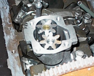
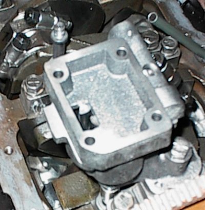
 Oil pump is Melling M55HV high volume for a 1990 Vortec 350 truck. The
Vortec pump comes with a 3/4" pickup tube instead of the usual 5/8", and a
matching cover. Here, I've clayed the pickup and found it needs to be bent up
a bit to clear the bottom of the pan. Normal for the high volume pumps, which
are longer than the standard pumps.
Oil pump is Melling M55HV high volume for a 1990 Vortec 350 truck. The
Vortec pump comes with a 3/4" pickup tube instead of the usual 5/8", and a
matching cover. Here, I've clayed the pickup and found it needs to be bent up
a bit to clear the bottom of the pan. Normal for the high volume pumps, which
are longer than the standard pumps.
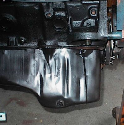
 The origin of the oil pan was unknown, but it and the pump collided. I
couldn't find anyone who'd ever run into that particular problem before.
Liberal application of the BFH was required to get clearance. Tape helped to
tell where to hit.
The origin of the oil pan was unknown, but it and the pump collided. I
couldn't find anyone who'd ever run into that particular problem before.
Liberal application of the BFH was required to get clearance. Tape helped to
tell where to hit.
 For some reason the hammer marks don't show up well on this picture, but I
shifted the wall out about a quarter of an inch.
For some reason the hammer marks don't show up well on this picture, but I
shifted the wall out about a quarter of an inch.
 Crank scraper was a Moroso part. It had to be ground and filed to fit, 1/32"
clearance to the crank and rods. The 400 crankcase is so tight you probably
don't really need a scraper; it's just a few teeth sticking here and there
from the pan rail, not a "scraper" like you'd think of for a 350.
Crank scraper was a Moroso part. It had to be ground and filed to fit, 1/32"
clearance to the crank and rods. The 400 crankcase is so tight you probably
don't really need a scraper; it's just a few teeth sticking here and there
from the pan rail, not a "scraper" like you'd think of for a 350.
 Self locking nuts and a little Loctite to make sure nothing comes adrift.
There's a lot of metal down in that pan, now...
Self locking nuts and a little Loctite to make sure nothing comes adrift.
There's a lot of metal down in that pan, now...
 The block decks were tapped 3/4 NPT - it takes a lot of oomph on the tap
wrench! - and the three round top water holes were blocked with Milodon plugs.
The block was then decked .020 to level them off and remove the oversize
chamfer the shop that bored it put on.
The block decks were tapped 3/4 NPT - it takes a lot of oomph on the tap
wrench! - and the three round top water holes were blocked with Milodon plugs.
The block was then decked .020 to level them off and remove the oversize
chamfer the shop that bored it put on.
Hard Blok filler was poured to the lower edge of the freeze plugs and then I
honed the block with a torque plate.
 The engine has been tanked and scrubbed with soap and water, but there's still
crud to be had.
The engine has been tanked and scrubbed with soap and water, but there's still
crud to be had.
 When I pulled the engine back apart I found that some of the Tech Line bearing
coatings had pulled off, despite tedious attention to detail when applying the
stuff. It wasn't the first time I'd had trouble with bearing coating. Seems
to work great on pistons, though.
When I pulled the engine back apart I found that some of the Tech Line bearing
coatings had pulled off, despite tedious attention to detail when applying the
stuff. It wasn't the first time I'd had trouble with bearing coating. Seems
to work great on pistons, though.
 I used naptha and Scotchbrite to remove the coating, but Jay decided he
wanted brand new bearings anyway, so these were boxed up and new bearings
installed.
I used naptha and Scotchbrite to remove the coating, but Jay decided he
wanted brand new bearings anyway, so these were boxed up and new bearings
installed.
 The timing mark on the damper was off a bit, so I found true TDC and made a
new mark. Chevys usually aren't off a whole lot on the timing marks.
The timing mark on the damper was off a bit, so I found true TDC and made a
new mark. Chevys usually aren't off a whole lot on the timing marks.
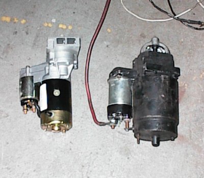 With over 11:1 compression, even the heavy duty GM starter had trouble turning
the 416 over. Jay bought a 2.5HP gear reduction starter from Speedway.
With over 11:1 compression, even the heavy duty GM starter had trouble turning
the 416 over. Jay bought a 2.5HP gear reduction starter from Speedway.
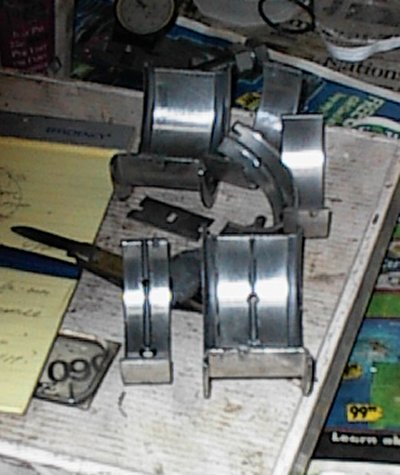
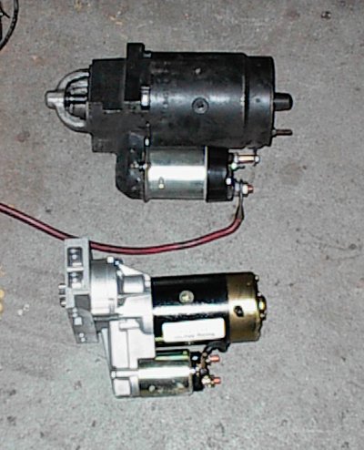 The size difference is obvious. Speedway sent extensive instructions,
shims, and spacers with the starter. It turned out I needed them!
The size difference is obvious. Speedway sent extensive instructions,
shims, and spacers with the starter. It turned out I needed them!
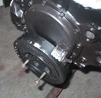
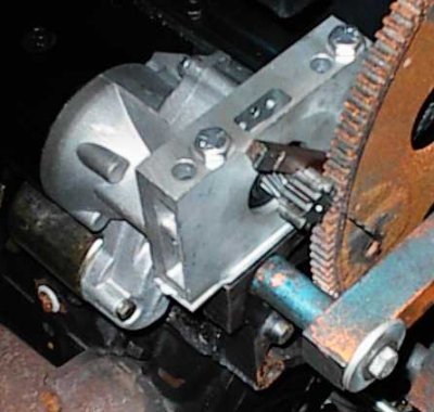 The starter wouldn't disengage properly. It turned out the pinion was too
close to the ring gear, and would bind up as soon as the Bendix threw it out.
I stacked all the shims I had, and it barely cleared - the tool bit is holding
it out so I can measure the clearance with a drill bit. I finally made spacer
plate from 1/8" aluminum so I didn't have to use so many individual starter
shims. It still took a few.
The starter wouldn't disengage properly. It turned out the pinion was too
close to the ring gear, and would bind up as soon as the Bendix threw it out.
I stacked all the shims I had, and it barely cleared - the tool bit is holding
it out so I can measure the clearance with a drill bit. I finally made spacer
plate from 1/8" aluminum so I didn't have to use so many individual starter
shims. It still took a few.
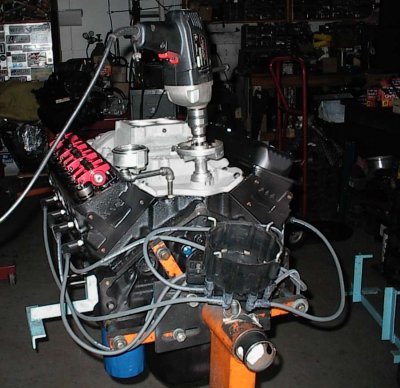 Insert the priming tool, this time remember to put the oil pressure gauge on
before spinning the oil pump...
Insert the priming tool, this time remember to put the oil pressure gauge on
before spinning the oil pump...
 Here we are, all set up and ready to fire. And now we have problems...
 I'd get an occasional pop, that was it. So I went through the usual checklist
- spark, fuel, plug wires in the right places, timing correct... then pulled
the valve covers off and rechecked the valve adjustment, etc.
I'd get an occasional pop, that was it. So I went through the usual checklist
- spark, fuel, plug wires in the right places, timing correct... then pulled
the valve covers off and rechecked the valve adjustment, etc.
 Finally said to hell with it, lifted it back up onto the engine stand, and
took it apart.
Finally said to hell with it, lifted it back up onto the engine stand, and
took it apart.
While the engine was apart, Jay decided he'd rather have one of those Kevko 7-quart dirt tracker pans. I ordered one in. The pickup tube was priced separately. For a few dollars more I got one of the Moroso pickup covers, which dispenses with the tube entirely. As usual, it turned into a project...
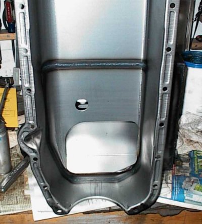 New Kevko pan. Asian made, but very nice stampings and clean TIG welds. T
sump isn't visible in this picture.
New Kevko pan. Asian made, but very nice stampings and clean TIG welds. T
sump isn't visible in this picture.
 Pull the original pump cover off, which holds the pickup tube and also houses
the pressure regulator.
Pull the original pump cover off, which holds the pickup tube and also houses
the pressure regulator.
 Pump side of the Moroso pickup. Slots are "anti-chatter grooves", trendy oil
pump stuff.
Pump side of the Moroso pickup. Slots are "anti-chatter grooves", trendy oil
pump stuff.
 New cover/pickup in position. Stuff at right is plunger and spring for oil
pressure regulator. It's regulated to 45 PSI, I found later. The standard
M55HV is set to 75 PSI. 45 is just fine, but since the engine had made 75 the
first time, it took a while to figure out why it didn't have as much oil
pressure the second time as it did the first time...
New cover/pickup in position. Stuff at right is plunger and spring for oil
pressure regulator. It's regulated to 45 PSI, I found later. The standard
M55HV is set to 75 PSI. 45 is just fine, but since the engine had made 75 the
first time, it took a while to figure out why it didn't have as much oil
pressure the second time as it did the first time...
 And here it all is, in place. Much better than the funky pickup tube the pan
manufacturer wanted me to use.
And here it all is, in place. Much better than the funky pickup tube the pan
manufacturer wanted me to use.
 A little modeling clay, pop the new pan on... and... rats. 1-1/2" or so of
clearance. That would leave more than two quarts in the pan, inaccessible.
A little modeling clay, pop the new pan on... and... rats. 1-1/2" or so of
clearance. That would leave more than two quarts in the pan, inaccessible.
 A piece of 1" aluminum bar stock from the "stuff" box, some longer bolts, some
work with the drill and the Dremel to make a hole to match the oil inlet hole
in the Moroso pickup cover...
A piece of 1" aluminum bar stock from the "stuff" box, some longer bolts, some
work with the drill and the Dremel to make a hole to match the oil inlet hole
in the Moroso pickup cover...
 Now we rub a Magic Marker all over the Moroso pickup casting, put some tape on
our aluminum block, bolt the two together, and whack the snot out of them with
a mallet. After taking them apart, there's a nice ink print in the tape.
Now we rub a Magic Marker all over the Moroso pickup casting, put some tape on
our aluminum block, bolt the two together, and whack the snot out of them with
a mallet. After taking them apart, there's a nice ink print in the tape.
 A little work with the Dremel tool, and now we have anti-chatter grooves in
the extension block.
A little work with the Dremel tool, and now we have anti-chatter grooves in
the extension block.
 The square corners on the block hit the oil pan. Some work with the belt
sander got the needed clearance. The Moroso casting didn't quite clear
either. Why this particular small block Chevy had oil pump clearance
problems is a mystery to me...
The square corners on the block hit the oil pan. Some work with the belt
sander got the needed clearance. The Moroso casting didn't quite clear
either. Why this particular small block Chevy had oil pump clearance
problems is a mystery to me...
 The modeling clay comes back out, and we have about 1/2" of clearance to the
bottom of the pan. Satisfactory.
The modeling clay comes back out, and we have about 1/2" of clearance to the
bottom of the pan. Satisfactory.
 Now we get to put all the stuff back together. Fender washers put even
pressure on the scraper, which is glued to the block before the pan gasket and
pan go on.
Now we get to put all the stuff back together. Fender washers put even
pressure on the scraper, which is glued to the block before the pan gasket and
pan go on.
 So I got it all back together, back on the stand, with the new ignition
switch, and it fired right up. I ran it for about an hour before breaking
down the setup.
So I got it all back together, back on the stand, with the new ignition
switch, and it fired right up. I ran it for about an hour before breaking
down the setup.
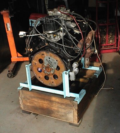
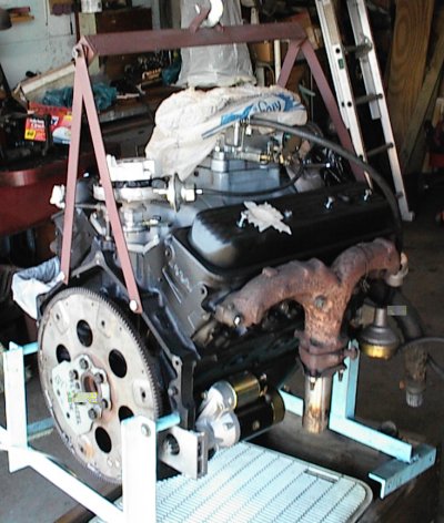
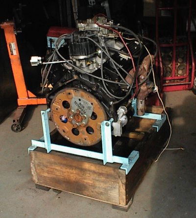
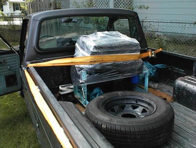 And here we are, wrapped in plastic and ready to go to Memphis. I loaned Jay
my run stand brackets for a while instead of making an engine cradle.
And here we are, wrapped in plastic and ready to go to Memphis. I loaned Jay
my run stand brackets for a while instead of making an engine cradle.
Next step, the joy of installation into a van...
M A X I M U M O V E R D R I V E R A C I N G E N G I N E S
416 CID small block Chevrolet for Jay Klahr, Memphis, Tennessee
begun November 1994
delivered June 2002
for 1975 Chevrolet LWD van
Engine run in on run stand before installation.
warranty: if it explodes, you can keep any pieces you can find
COMPONENTS ---------------------------------------------------------------
crankshaft:
stock Chevrolet 3.75" 400, 2-piece rear main seal, cast
mains - .020" undersize
rods - .030" undersize
externally balanced
journals polished
pistons:
Keith Black KB168
D-dish, 22cc
.060 oversize, 4.185" diameter
1.43" pin height
rings:
Total Seal gapless, file fit, 5/64, 5/64, 3/16
side clearance .003 top and second
ring gaps .012 top, .012 second, .016 oil
rods:
5.7 Chevrolet
bearings .030
rod side clearances .012
resized big ends (minimum size)
ARP rod bolts
block:
Chevy 400, four bolt, two piece rear main
bored +.060
honed to .0015 piston/wall clearance, #600 wall finish, torque plate
new brass core plugs (blue silicone sealer)
new cam bearings (King)
head bolt holes chased
tapped and Moroso screw-in deck plugs installed
cut .020 to zero deck height
screw-in oil passage plugs
rear main oil drainback mods
grooved upper main saddles
deburr
Hard Blok:
freeze plugs are 3-5/8 down from deck to bottom of freeze plugs
all plugs same level (350 aren't)
water jacket depth avg. 5-5/8, both sides, less than 1/8 variation
jackets go almost all the way down to bottom of bores
heads:
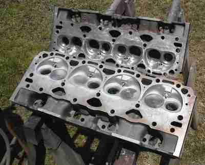
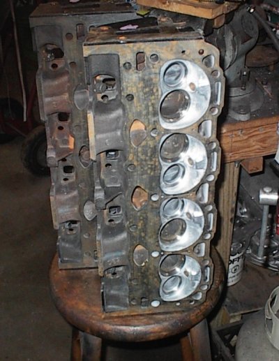
new Chevrolet 916 casting Vortec
64cc chambers
polished, sandblasted, ceramic coated chambers and exhaust ports
2.02/1.60 one-piece stainless steel valves
3-angle valve job (stock is 1-angle), vacuum checked
exhaust valves 20 degree front cut, 20 degree back cut
intake valves front cut 15 degrees
guide bosses cut down for spring and keeper clearance
Iskenderian valve springs with dampers
Iskenderian chrome moly retainers
bronze guide liners, .0015" clearance
drilled and tapped for early intake manifold bolt pattern
CBC-2 thermal barrier ceramic coated valves
cut for screw-in studs
Isky 7/16" screw-in studs
Isky 1.6:1 aluminum roller rockers
timing set:
Iskenderian two-gear, reverse rotation helical gear drive
Isky needle bearing block protector
Isky roller thrust stop
cam:
Iskenderian hydraulic roller 217/217 @.050, 108 lobe center
.517/.517 with 1.6 rockers
reverse rotation (for two gear drive)
steel cam, cast iron gear and last journal brazed on
#5 cam journal undersize; Isky bearing 1.862 OD stock 1.869 OD
made bronze rear cam bearing, sized for .0015" oil clearance
Iskenderian hydraulic roller lifters
custom length Howard 5/16" pushrods
ignition:
GM HEI, rebuilt
Iskenderian cast iron, reverse rotation cam gear
shaft lengthened for .030" clearance to oil pump
distributor thrust *down*
induction:
Offenhauser Dual Port 360 intake
Carter ThermoQuad carburetor
oiling:
Melling M55HV high volume pump
Moroso pickup cover
regulator set to 45 PSI
1" extension for pickup cover, 3/8" pan clearance
Kevko 7-quart pan
miscellaneous:
400 harmonic balancer
bolt-on bobweight in back
Victor graphite wirelock head gaskets
balance:
.02F/.04R oz-in
===========================================================================
TORQUE SPECIFICATIONS -----------------------------------------------------
--------torque---------------spec--------------thread----lube--------------
rod bolts
torqued to 45 ft-lb (Chevrolet spec 45) 3/8-24 oil
note: 1) step 1: 25 ft-lb (both bolts)
step 2: 45 ft-lb (then finish up)
main cap bolts
torqued to 70 ft-lb (Chevrolet spec 60-70) 7/16-14 oil
note: 1) use moly grease under bolt head
2) step 1: 50 ft-lb
step 2: 70 ft-lb (reverse pattern)
head bolts
torqued to 70 ft-lb (Chevrolet spec 65-72) 7/16-14 oil
note: 1) block is through tapped, sealer needed
2) step 1: 50 ft-lb
step 2: 70 ft-lb (reverse pattern)
damper (harmonic balancer) bolt
(Chevrolet spec 70-90) 5/8-18 oil
note: use automatic transmission fluid as lubricant when pressing damper on
flexplate bolts
(Chevrolet spec 75-85) sealer
note: 1) see drawing for pattern
intake manifold bolts
(Chevrolet spec 23-25) 5/16-18 sealer
note: 1) see drawing for pattern
exhaust manifold bolts
(Chevrolet spec 18-24) 5/16-18 antiseize
note: 1) see drawing for pattern
timing chain sprocket bolts
torqued to 40 ft-lb (Chevrolet spec 40-45) 3/8-16
(Fel-Pro Grey Bolt Prep)
oil pan bolts
(Chevrolet spec 7-9) 1/4-20 oil
(Chevrolet spec 9-11) 5/16-18 oil
oil drain plug
(Chevrolet spec 15-25) 1/2-20 oil
water pump bolts
(torque 35) 3/8-16 sealer
timing cover bolts
(torque 12-18) 5/16-18 oil
1/4 NPT threaded oilway plugs Loctite Pipe Sealer With Teflon
or silicone sealer, Teflon pipe sealer
oil pump cover plate
(Chev spec 9-11) 1/4-20 oil
oil pump body
(torque 55) 7/16-18 oil
spark plugs
14mm antiseize
bottom pulley to damper
(Chevrolet spec 35-50) oil
valve cover
(Chevrolet spec 3-5) 1/4-20 oil
===========================================================================
assembly lubricants:
rod bearings: GM Engine Oil Supplement
rings: Unilube two stroke oil
cylinder walls: Mobil 1 5w30
piston skirts: Mobil 1 5w30
wrist pins: Mobil 1 5w30
head bolts - threads: Teflon sealer
main bolts - threads: 30wt ND
head, main bolts - under head: moly grease
rod bolts: 30wt ND
cam bolts: Fel-Pro Grey Bolt Prep
cam lobes: moly grease
cam journals: Fel-Pro assembly lube
cam distributor drive gear: moly grease
crankshaft rear oil seal: Mobil 1 5w30
INSTALLATION: ------------------------------------------------------------
Don't forget the ground strap connecting the engine to the chassis. If
it is broken or missing, make another out of at least 10 guage wire.
Make sure the battery is grounded to both the chassis and the engine. It
probably has a big wire to the block or head and some little cheesy wire
from the intake manifold to the firewall. Use at least #4 (battery cable
size) direct from the negative post to the starter and to the chassis.
Your starter and headlights will appeciate it.
Make sure the battery is fully charged before trying to start a new motor.
RUN-IN: -----------------------------------------------------------------
Make sure you don't have any loose wires or hoses in the way of the fan
before firing the engine. It is a great temptation to just start it up
with nonessentials hanging hither and yon.
Pour in 5 quarts of your favorite brand of non-synthetic oil, 10-30 or 10-40
weight, one bottle of General Motors Engine Oil Supplement, and screw
on an oil filter. It probably wouldn't hurt to fill the filter before
putting it on.
Your motor is already run-in. Do the first oil change at 100 miles, then
at 3 to 5 thousand mile intervals afterward
Oil Viscosity:
Use the lowest viscosity oil required to maintain hot idle oil pressure of
at least 25 psi. This will circulate the maximum amount of oil through the
bearings. Very thick oil just goes right through the popoff valve built
into the oil pump and you can be starving the bearings while the guage
happily reads 60-80 PSI.
===========================================================================