Author: Dave Williams; dlwilliams=aristotle=net
Images and text used by permission of James Gibat-Thoroski, based on a snapshot of his web site Project RSX on November 2000.
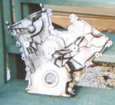
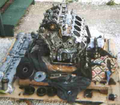
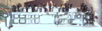
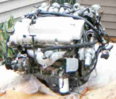 Motor as it arrived on its crate.
This shows the front/passenger side of the engine, note the vertical oil
filter with the oil cooler above it. The wire near the oil filter is the oil
pressure sending unit. Coolant comes out of the block through the oil cooler
and an external line takes it to the water pump. To the left under the oil
fill cap is the AC compressor. On the other end, the rear/driver's side is the
water pump. The thermostat is in the water pump housing. Tube going to the top
of the exhaust manifold is the Secondary Air Injection Valve tube. Above the
oil filter, on the head, to the right of the exhaust manifold is the CMP -
camshaft position sensor.
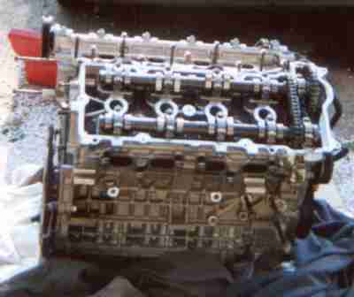
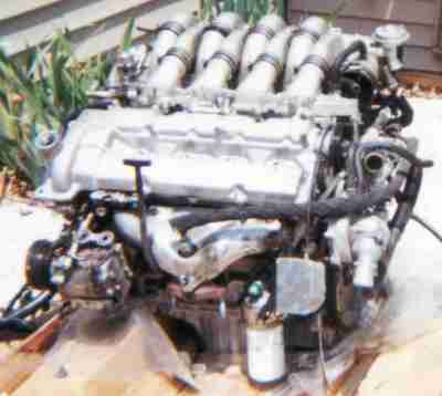 Motor as it arrived on its crate without its cover.
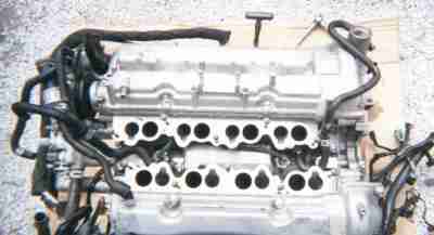
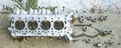
This photo is of the the front/driver's side of the motor. This is with the cover removed showing the valve cover. Looking down the centre of the valve cover you can see the holes where the spark plugs are. They are centered directly in the center of the combustion chamber.
Hanging directly at the above right of the oil filter is the IRMC box. This controls the secondary valves that allow the motor to breathe more above 3500RPM. Once at 3500RPM this box opens the secondaries, much like a carb, and allows air to pass through to the other intake valves.
The water pump assembly is to the right.
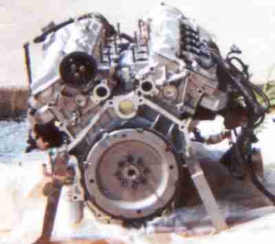
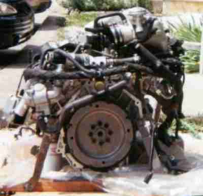 This photo is of the rear/driver's side of the motor. The upper left side is
the water pump. You can see how the intake and surge tank cover the entire
passenger side/rear of the motor. You can also see the flexplate from this
angle. It has a hole through it right into the back of the crank. Perfect
for a manual transmissions! You'll notice also that the bellhousing pattern
isn't perfectly around the entire block. There is room on the right side for
a regular starter, I just hope there is enough room!
This photo is of the rear/driver's side of the motor. The upper left side is
the water pump. You can see how the intake and surge tank cover the entire
passenger side/rear of the motor. You can also see the flexplate from this
angle. It has a hole through it right into the back of the crank. Perfect
for a manual transmissions! You'll notice also that the bellhousing pattern
isn't perfectly around the entire block. There is room on the right side for
a regular starter, I just hope there is enough room!
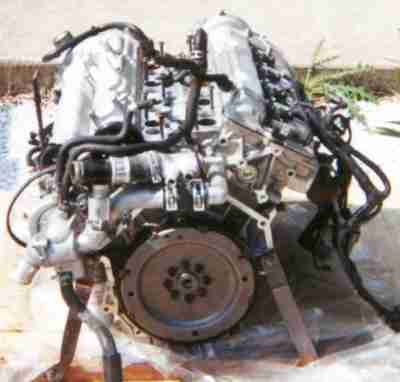
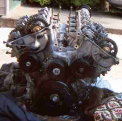
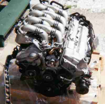 Here is the SHO V8 from the front/passenger side. Here you can see the wiring
harness to the left as well as the A/C compressor on the right. One
serpentine belt wraps around all of these pulleys on the front. A pretty
small and compact package. Directly in the center of the motor at the top of
the front cover you can see the power steering pump without its pulley.
Here is the SHO V8 from the front/passenger side. Here you can see the wiring
harness to the left as well as the A/C compressor on the right. One
serpentine belt wraps around all of these pulleys on the front. A pretty
small and compact package. Directly in the center of the motor at the top of
the front cover you can see the power steering pump without its pulley.
Just above the power steering pump to the left you can see the shiny chrome
fuel pressure regulator.
 This is the surge tank (upside down) The large opening goes to the throttle
body. For our project however, a large stainless steel tube will be entering
here from the twin turbos. This is actually a great intake for the project as
all you have to do is form the pipe and clamp it on. Also with the way the
intake is made it might be pretty easy to shorten or lengthen the intake
runners to tune the motor for high or low RPM.
This is the surge tank (upside down) The large opening goes to the throttle
body. For our project however, a large stainless steel tube will be entering
here from the twin turbos. This is actually a great intake for the project as
all you have to do is form the pipe and clamp it on. Also with the way the
intake is made it might be pretty easy to shorten or lengthen the intake
runners to tune the motor for high or low RPM.
 This shows the rear/passenger side of the engine. The four circles through the
center of the valve cover are the coil-on-plug ignition coils. I would LOVE to
keep these coils if I can for our project but I am not sure if I'll be able to
get an ignition system to work with it as the original SHO V8 ignition was all
controlled by the EEC-V. I am going to try and work something with
Electromotive if I can. Perhaps they can ship me a unit without thier coils
and set something up that will fire my coils instead.
This shows the rear/passenger side of the engine. The four circles through the
center of the valve cover are the coil-on-plug ignition coils. I would LOVE to
keep these coils if I can for our project but I am not sure if I'll be able to
get an ignition system to work with it as the original SHO V8 ignition was all
controlled by the EEC-V. I am going to try and work something with
Electromotive if I can. Perhaps they can ship me a unit without thier coils
and set something up that will fire my coils instead.
You can see most of the wiring harness here.
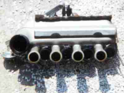
On top you can see the individual runners into the intake. The surge tank
clamps on to these.
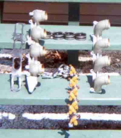 These are the upper intake manifolds. Pretty simple. I think it might be
pretty easy to get a set of custom intakes made and mount a few downdraft
Webers to them.
These are the upper intake manifolds. Pretty simple. I think it might be
pretty easy to get a set of custom intakes made and mount a few downdraft
Webers to them.
The orange things in the middle are the 19 lb/hr fuel injectors which screw into the lower intake manifold.
Note the odd oval shaped holes in the gasket - oval for the siamese intake
ports in the lower intake manifold. The manifolds come down to the IMRC and
then it widens to allow air into both intake runners for the valves.
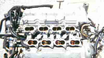 This is the top view of the engine showing the IMRC manifold in place. The two
rows of holes down the center are where the fuel injectors push in. The
right/passenger side of the engine is closest, note the dipstick on the far
side. The close side shows the secondaries being closed. These lead to the
secondary intake valve. These are the secondaries that open at about 3500 rpm.
They are larger than the primary intake port though the intake valves are the
same size. Some say this valve closes near redline to limit RPM and keep the
SHO Taurus out of trouble. In our project this won't be a problem as the
Electromotive unit will have a rev limiter.
This is the top view of the engine showing the IMRC manifold in place. The two
rows of holes down the center are where the fuel injectors push in. The
right/passenger side of the engine is closest, note the dipstick on the far
side. The close side shows the secondaries being closed. These lead to the
secondary intake valve. These are the secondaries that open at about 3500 rpm.
They are larger than the primary intake port though the intake valves are the
same size. Some say this valve closes near redline to limit RPM and keep the
SHO Taurus out of trouble. In our project this won't be a problem as the
Electromotive unit will have a rev limiter.
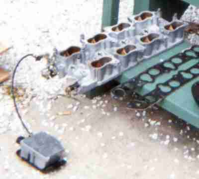 This is the IMRC intake manifold removed from the engine valley. It still has
the IMRC deactivation motor attached. Note the gaskets have a relief on one
port for the fuel injector. This allows the intjector to get a straight shot
at the intake valve. This will be of no value in our project. I will get the
ports ported as best I can. I've even thought about bigger secondaries.
Shouldn't be hard to port out the IRMC and add larger butterflies from a carb
of the same size butterfly. Something to try anyways.
This is the IMRC intake manifold removed from the engine valley. It still has
the IMRC deactivation motor attached. Note the gaskets have a relief on one
port for the fuel injector. This allows the intjector to get a straight shot
at the intake valve. This will be of no value in our project. I will get the
ports ported as best I can. I've even thought about bigger secondaries.
Shouldn't be hard to port out the IRMC and add larger butterflies from a carb
of the same size butterfly. Something to try anyways.
Soon I will be testing the IMRC box. I want to see if you apply 12V to the
box if the secondaries will open. I am expecting them to do so.
 With the lower intake manifold removed one can see the two green knock
sensors, one on each side of the box whish is the crankcase oil separator.
Note that the water pump is still attached on the left side of the photo. On
the right of the photo is a hole where the PS pump would be in the crotch of
the V between the heads.
With the lower intake manifold removed one can see the two green knock
sensors, one on each side of the box whish is the crankcase oil separator.
Note that the water pump is still attached on the left side of the photo. On
the right of the photo is a hole where the PS pump would be in the crotch of
the V between the heads.
 The mess above the flexplate is water plumbing. The actual pump is to the
left. The lower hose carries water into each head from the water pump. The
upper hose is the hot water return from the center of the block which goes to
the radiator, heater core and throttle heater.
The mess above the flexplate is water plumbing. The actual pump is to the
left. The lower hose carries water into each head from the water pump. The
upper hose is the hot water return from the center of the block which goes to
the radiator, heater core and throttle heater.
The SHO V8 is unique as it sends coolant to the heads first and then through
the block. This is also found on the LS1 and LT1 V8s from Chevrolet. This is
the first and only motor to have this cooling arrangement from Ford.
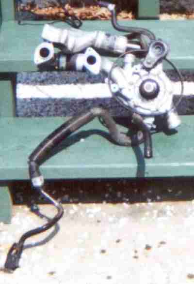 This is the back side of the water pump. The lower hose carries water into
each head from the water pump. The upper hose is the hot water return from the
center of the block which goes to the radiator, heater core and throttle
heater. Note the pulley, which runs off the intake camshaft and the belt
tension above it.
This is the back side of the water pump. The lower hose carries water into
each head from the water pump. The upper hose is the hot water return from the
center of the block which goes to the radiator, heater core and throttle
heater. Note the pulley, which runs off the intake camshaft and the belt
tension above it.
There has been some controversy about the water pump being driven off the
intake cam. I am not sure if this adds any undo stress to the cam or not. I
am hoping to get an underdrive pulley for the water pump so that it doesn't
put as much strain on the motor. With a large aluminum radiator it might
relieve some of that stress.
 This is the same view with water pump removed. You can see the big holes
which feed coolant to the heads, in between them is a whole in the block you
can not see which is the water return. It is flush like a thermostat would be
on a Chevrolet small block V8.
This is the same view with water pump removed. You can see the big holes
which feed coolant to the heads, in between them is a whole in the block you
can not see which is the water return. It is flush like a thermostat would be
on a Chevrolet small block V8.
In the center is the rear plug for the balance shaft above the flywheel.
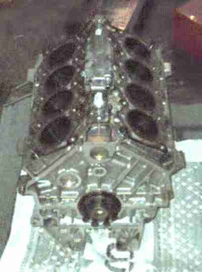
Note the proportion of the block with the big DOHC heads, and 60 degree V construction. If it were a 90 degree V it would be wider but not as tall over all. The 60 degree V8 is much lighter and more compact than a 90 degree V8.
This is what we need in our project. A small, light weight, narrow, compact
engine. This SHO V8 has it all!
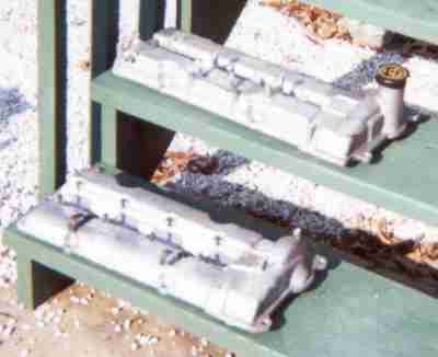 These are the cast valve covers. They are not stamped steel, aluminum or
plastic like on many other motors. These are cast out of aluminum and are
a lot heavier than most valve covers. The gaskets are rubber and reuseable.
These are the cast valve covers. They are not stamped steel, aluminum or
plastic like on many other motors. These are cast out of aluminum and are
a lot heavier than most valve covers. The gaskets are rubber and reuseable.
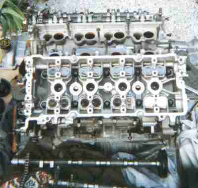
 Here is the passenger side/rear head with the valve cover off.
You can see the cams, intake on top and exhaust on the bottom. The cams are hollow tubes with the lobes glued on. The lobes are placed in a jig and the tube is place in the center. A ball is rammed down the center which expands the cam tube and fixes the lobes on the shaft. A glue makes the arrangement permanent. Down the center, like a Hemi are the 4 central spark plugs in their wells. Each little timing chain has it's own tensioner. The oil passage from each side of the block lubricates the tensioner first then has two galleries on under each camshaft that lubricates each "bearing". The camshaft has no bearing shell, the camshaft touches finished head surface.
Check out the cool webbing on the block exterior. The aluminum block and heads are is not as strong as an iron would be of the same dimensions. Instead of making a thicker and heavier bock the block is webbed externally for strength which results in a engine 100s of pounds lighter than a iron V8 of the same output.
Just looking at it gives me technolust.
 Missing are the AC compressor on the right, power steering pump on top in the
crotch of the V, alternator on the left and a drive belt tensioner which lives
under the alternator.
Missing are the AC compressor on the right, power steering pump on top in the
crotch of the V, alternator on the left and a drive belt tensioner which lives
under the alternator.
The center crank snout pulley is the only one changed when going to an
underdrive pulley. Just above its centerline on the right side is the
crankshaft position sensor. It maybe not visible in the shadows. One can see
the asymmetrical chain drive system. The V8 chain drive in contrast should
last as long as the car.
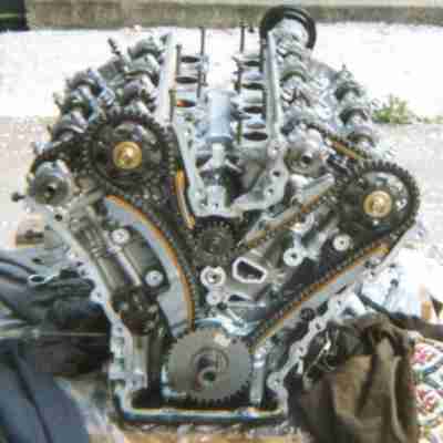 This is a more revealing photo of the chains that drive the cams. The upper
center in the crotch of the Vee is the balance shaft. The intake cams are
always in the center and the exhaust cams are toward the outside. The cams
must have large sprockets because the turn only 1/2 as fast as the crankshaft.
On the block, above and to the left of the crank snout is the timing chain
sprocket tensioner, which gets as much oil as the mains. The "tube" cast into
the block above the timing chain sprocket tensioner is the oil main gallery
going to the head. Another like it is visible on the other side.
This is a more revealing photo of the chains that drive the cams. The upper
center in the crotch of the Vee is the balance shaft. The intake cams are
always in the center and the exhaust cams are toward the outside. The cams
must have large sprockets because the turn only 1/2 as fast as the crankshaft.
On the block, above and to the left of the crank snout is the timing chain
sprocket tensioner, which gets as much oil as the mains. The "tube" cast into
the block above the timing chain sprocket tensioner is the oil main gallery
going to the head. Another like it is visible on the other side.
Where the crank pulley used to be you can see the trigger pulse wheel. This is
what the crank shaft position sensor reads to tell the EEC-V where the engine
is in it's rotation. It will be replaced or reused with the Electromotive
igition system.
 This is the timing chain cover, on can see the front main seal, where the
crank snout sticks out. To the right of the front main seal is the crankshaft
position sensor.
This is the timing chain cover, on can see the front main seal, where the
crank snout sticks out. To the right of the front main seal is the crankshaft
position sensor.
Looking at this, some how I will have to have motor mounts attached. In our
project we plan to have motor mount plates. Usually on normal V8s you can
attach them to the front of the head or through the front water pump. This
SHO V8 is a lot different in this respect. I am sure I will be able to figure
something out.
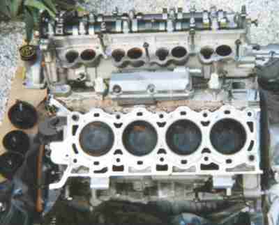
 With the camshafts removed one can see the bucket shims which move the valves
and the tops of the sparkplugs which are way down in the wells. No chance of
them getting much air. Note the absence of cam bearing half shells. Camshafts
must be removed to access 10 bolts that hold the head down. One can see the
oil hole for the tensioner on the left.
With the camshafts removed one can see the bucket shims which move the valves
and the tops of the sparkplugs which are way down in the wells. No chance of
them getting much air. Note the absence of cam bearing half shells. Camshafts
must be removed to access 10 bolts that hold the head down. One can see the
oil hole for the tensioner on the left.
There are only 10 bolts that hold down the head, which means 4 bolts per
cylinder. Pretty typical of Ford. This can contribute to problems with head
gasket sealing. A lot of SHO V8 owners probably havn't experienced this as
they are just running their stock motors. I guess we'll find out when we put
on our twin turbos.
 One can see the oil separator better with the knock sensors better in this
shot and the siamese water ports to the right in the crotch of the V.
One can see the oil separator better with the knock sensors better in this
shot and the siamese water ports to the right in the crotch of the V.
On the head gasket surface, the large round holes are all head bolt holes. Everything else is a water passage except the small round hole on the left which is a oil passage. Note the abundance of water holes on the lower side, where the exhaust valves are in the head.
Towards the right side of the motor you can see in the center the hole in the face of the V. This is where all the coolant comes out of the motor. The coolant flows through the heads, then the block and comes out there.
Another interesting note is how high the deck hieght is. It doesn't come up
much higher than the center "valley". On a lot of older V8s, the deck would
come up much higher. I think this gives the SHO block added strength as it's
one compact piece of aluminum without any extremities hanging out.
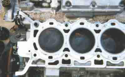 It may be difficult to see but the piston tops are near flat with a small
shallow dish in the center. The dish an indication reducing the compression
ratio. the combustion chamber in the head is a measly 39cc. This is
incredbly small. With a flat top piston I am sure the compression ratio would
be close to, if not over, 11:1. The stock compression ratio is 10:1.
It may be difficult to see but the piston tops are near flat with a small
shallow dish in the center. The dish an indication reducing the compression
ratio. the combustion chamber in the head is a measly 39cc. This is
incredbly small. With a flat top piston I am sure the compression ratio would
be close to, if not over, 11:1. The stock compression ratio is 10:1.
Note the absence of valve relief eyebrows on the piston tops. Four valve
engines require less valve lift than 2 valve engines for the same port flow.
Oil passage is visible as small round hole on left side.
 Intake valve run across the top row of the head in this photo. Their valve
stems are all parallel. The exhaust valves are smaller and run across the
bottom. Note the emphasis of cooling passages on the exhaust side of the head.
Also visible are the bucket shims and a long head bolt. So far I haven't seen
much use of studs, It looks like the engine is put together with bolts not
studs so far. I wonder what the lower end uses. The orange thing on the right
side of the head is a chain guide.
Intake valve run across the top row of the head in this photo. Their valve
stems are all parallel. The exhaust valves are smaller and run across the
bottom. Note the emphasis of cooling passages on the exhaust side of the head.
Also visible are the bucket shims and a long head bolt. So far I haven't seen
much use of studs, It looks like the engine is put together with bolts not
studs so far. I wonder what the lower end uses. The orange thing on the right
side of the head is a chain guide.
You can see the spark plugs in the center of each combustion chamber.
 Here on can see just how high head is. On the nose of the crank snout is the
crank driven "G-rotor" oil pump. Above that one can see the balance shaft
sprocket.
Here on can see just how high head is. On the nose of the crank snout is the
crank driven "G-rotor" oil pump. Above that one can see the balance shaft
sprocket.
You can see how compact the block is itself. I know how the short block goes
together. This should be one strong little motor. 600 to 700 HP would
probably be the max.
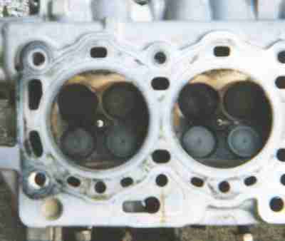 Here is a great close up of the combustion side of the head. I should be
getting some clearer ones later. Intake valves on top, center spark plug,
smaller exhaust valves on the bottom. The four round holes in the corners are
bolt holes. The oblong holes are for coolant.
Here is a great close up of the combustion side of the head. I should be
getting some clearer ones later. Intake valves on top, center spark plug,
smaller exhaust valves on the bottom. The four round holes in the corners are
bolt holes. The oblong holes are for coolant.
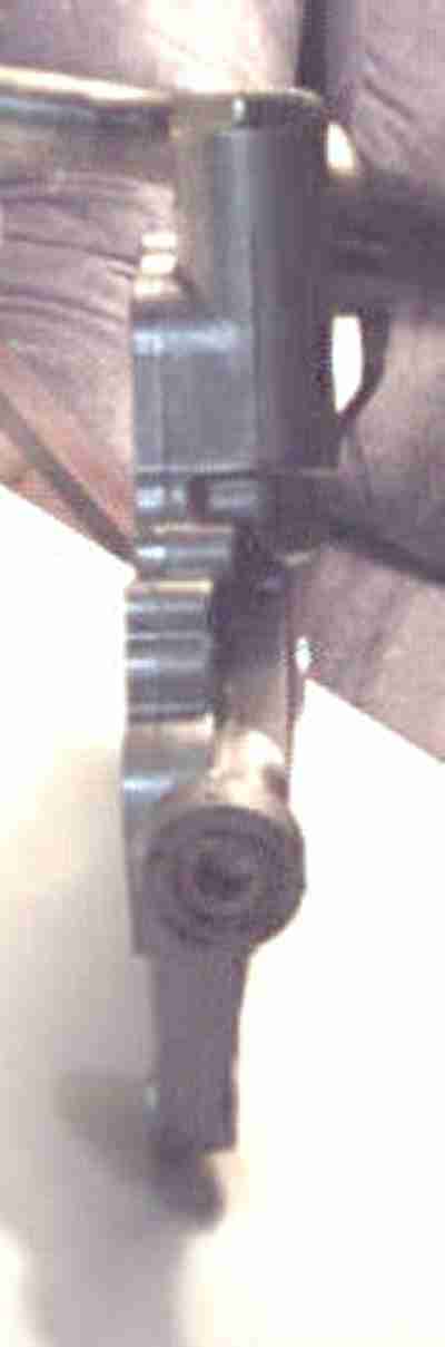
 Close up of the power steering pump without its pulley.
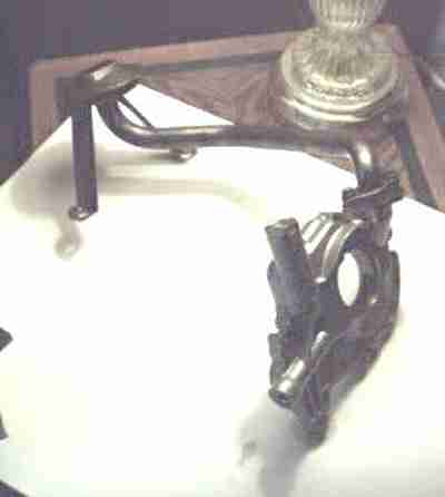
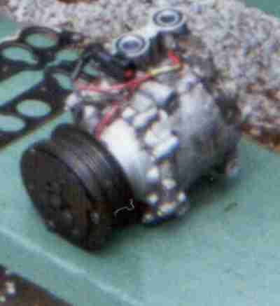 A/C Compressor
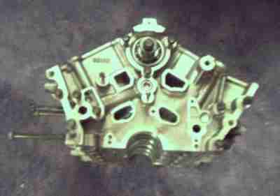 This is the front of the block after being completely disassembled. The only
thing left in it is the balance shaft. You can tell this block is meant for
racing. It's cast for purpose. It's extremely light weight and very small.
The bolts on the side are for the alternator bracket. It's bolted to the side
of the block. The aluminum is also very soft. It's not very hard to put a
nick or mark into it.
This is the front of the block after being completely disassembled. The only
thing left in it is the balance shaft. You can tell this block is meant for
racing. It's cast for purpose. It's extremely light weight and very small.
The bolts on the side are for the alternator bracket. It's bolted to the side
of the block. The aluminum is also very soft. It's not very hard to put a
nick or mark into it.
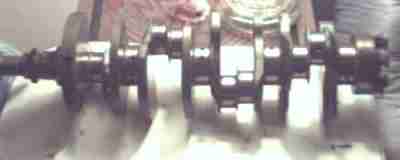 A picture of the crank. Each connecting rod has its own rod journal. They
are on the same throws but they are offset slightly. It's a fairly beefy
unit. The counterweights are huge! The end of the crank has 8 bolts. There
isn't any balance to it like a 5.0 V8. It's all internally balanced with help
from the balance shaft.
A picture of the crank. Each connecting rod has its own rod journal. They
are on the same throws but they are offset slightly. It's a fairly beefy
unit. The counterweights are huge! The end of the crank has 8 bolts. There
isn't any balance to it like a 5.0 V8. It's all internally balanced with help
from the balance shaft.
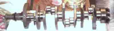 Another clearer picture of the crank. You can see in cross drilling of the
crank a little better in this picture. The mains and the rod journals have
been cross drilled at the factory for better oiling of the mains and the rod
journals. One less machining process I won't have to pay for!
Another clearer picture of the crank. You can see in cross drilling of the
crank a little better in this picture. The mains and the rod journals have
been cross drilled at the factory for better oiling of the mains and the rod
journals. One less machining process I won't have to pay for!
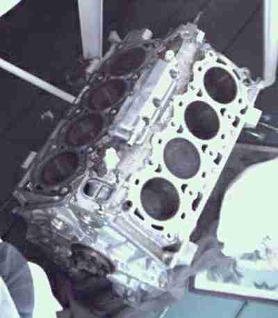
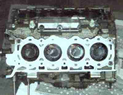
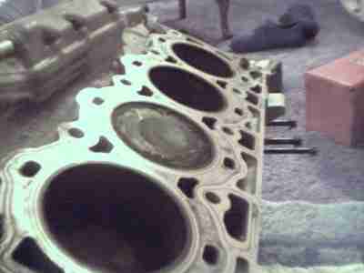 Here is a great picture of the block deck and the disked piston. There are no
valve reliefs, only a small dish to reduce compression slightly. They head's
have a 39cc combustion chamber and with a flat top piston the compression
would probably be 10.5 or 11.0:1. You can see all the coolant holes where the
coolant enters from the heads. The 3 large holes you see along the bottom of
the block(right side) are the oil drain holes. The oil that goes up into the
heads are then drained down into the oilpan through those holes.
Here is a great picture of the block deck and the disked piston. There are no
valve reliefs, only a small dish to reduce compression slightly. They head's
have a 39cc combustion chamber and with a flat top piston the compression
would probably be 10.5 or 11.0:1. You can see all the coolant holes where the
coolant enters from the heads. The 3 large holes you see along the bottom of
the block(right side) are the oil drain holes. The oil that goes up into the
heads are then drained down into the oilpan through those holes.
 Another angle on the inside of the short block.
You can see some of the cross drilling on the rod journals as well as some oil
drain back holes in the block up inside the block where some of the
counterweights are. Along the side of the outside of the block you can see
some of the webbing.
 Knock Sensors. They won't be used in our application unless the ignition
system I get can take advantage of them but I doubt it. There are two, one in
the front and one in the back of the block.
Knock Sensors. They won't be used in our application unless the ignition
system I get can take advantage of them but I doubt it. There are two, one in
the front and one in the back of the block.
Some people on the V8 SHO mailing list that their motors ping on 87 octane
fuel. These might be the problem. If they are not sensitive enough or not
working the computer will not pull timing out and the motor with detonate.
It's my contention with such small combustion chambers, high 10:1 compression
and a high revving nature, 93 octane or higher should be used. With the
propane we are using octane won't be a problem. It's rated at 110.
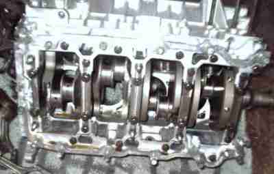
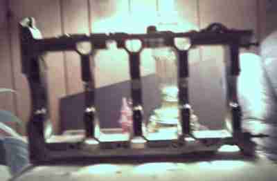
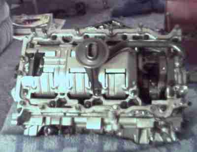
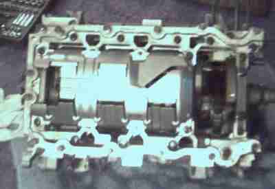
 It's always hard to describe this thing. This is the bottom of the motor. On
most motors all the main bearing journals that hold the crank in are seperate.
On motors like the 5.0 V8 from the Mustang, all the mains are seperated. In
the SHO V8 they are all tied together. This strengthens the bottom end of the
motor by tieing all the mains together to one main web. This resists the
mains from walking and allowing a spun bearing and all other kinds of
problems. With the kind of power we'll be making, this will help it all stay
together.
It's always hard to describe this thing. This is the bottom of the motor. On
most motors all the main bearing journals that hold the crank in are seperate.
On motors like the 5.0 V8 from the Mustang, all the mains are seperated. In
the SHO V8 they are all tied together. This strengthens the bottom end of the
motor by tieing all the mains together to one main web. This resists the
mains from walking and allowing a spun bearing and all other kinds of
problems. With the kind of power we'll be making, this will help it all stay
together.
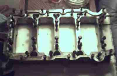
 Another picture of the mains/girdle from the bottom of the motor. This is
showing it from the side. It's pretty thick with a lot of webbing. You could
say the block is two pieces. The main upper and the lower pictured here.
Another picture of the mains/girdle from the bottom of the motor. This is
showing it from the side. It's pretty thick with a lot of webbing. You could
say the block is two pieces. The main upper and the lower pictured here.
 Another picture of the mains/girdle. This time it's standing up so you can
see the basic shape. The mains are actually quite thick for such a small
motor.
Another picture of the mains/girdle. This time it's standing up so you can
see the basic shape. The mains are actually quite thick for such a small
motor.
 The oil pickup that sits on the oil pan.
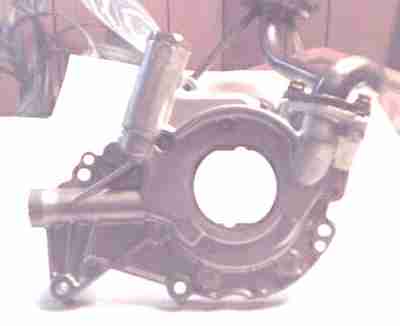 The oil pump. This is a gerotor design. It is bolted to the front of the
crank snout and is turned by the crank. It's supposed to be VERY effcient.
You can see how it's indexed to the crank and the pick up is bolted to the
pump.
The oil pump. This is a gerotor design. It is bolted to the front of the
crank snout and is turned by the crank. It's supposed to be VERY effcient.
You can see how it's indexed to the crank and the pick up is bolted to the
pump.
 The oil pump from the side. It's very thin to fit between the front main and
front cover.
The oil pump from the side. It's very thin to fit between the front main and
front cover.
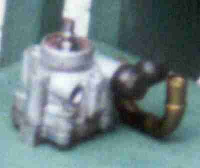
 This is the complete oil pump assembly. It will be completely replaced when
the motor goes back together. The motor had an oiling problem to begin with
and replaceing the pump and pick up would be cheap insurance. I don't know
how I will be able to prime the motor before I start it up.
This is the complete oil pump assembly. It will be completely replaced when
the motor goes back together. The motor had an oiling problem to begin with
and replaceing the pump and pick up would be cheap insurance. I don't know
how I will be able to prime the motor before I start it up.
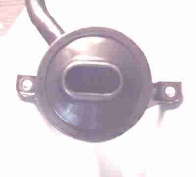
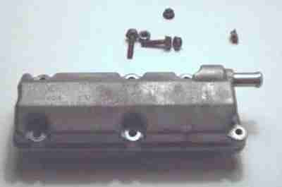 Oil Seperator. This is actually a part of the PCV System. It helps take out
the gases and pressure from in the block and lets it circulate back through
the motor to be burnt and sent out the exhaust.
Oil Seperator. This is actually a part of the PCV System. It helps take out
the gases and pressure from in the block and lets it circulate back through
the motor to be burnt and sent out the exhaust.
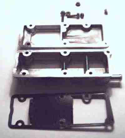
Oil Seperator opened up.
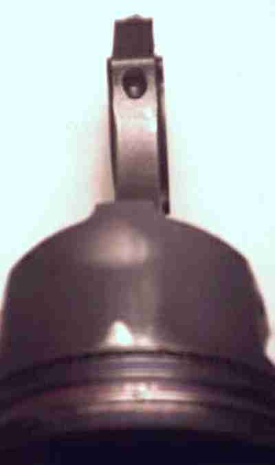
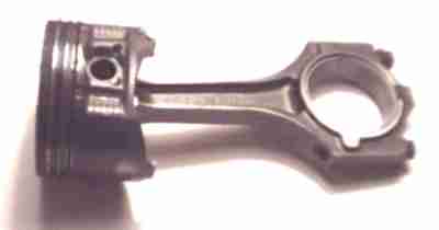 Here is the piston and rod assembly. The piston is a short skirt design. The
compression height is approximately 1.18". That is pretty small. This means
that the pin that holds piston to the rod is 1.18" from the centre of that pin
to the top of the piston. Besides the other Duratech engines (2.5 & 3.0 V6),
this is the only engine I know with a short skirt. Again, comparing it to the
5.0 V8, the compression height is around 1.7". A lot of stroked motors use
these types of pistons. This causes the piston to rod a little more than the
normal longer skirt pistons. Looking at the picture you can see the smudge on
the piston skirt showing that the skirt has been contacting the cylinder wall.
This is a piston with only 13,000 miles on it.
Here is the piston and rod assembly. The piston is a short skirt design. The
compression height is approximately 1.18". That is pretty small. This means
that the pin that holds piston to the rod is 1.18" from the centre of that pin
to the top of the piston. Besides the other Duratech engines (2.5 & 3.0 V6),
this is the only engine I know with a short skirt. Again, comparing it to the
5.0 V8, the compression height is around 1.7". A lot of stroked motors use
these types of pistons. This causes the piston to rod a little more than the
normal longer skirt pistons. Looking at the picture you can see the smudge on
the piston skirt showing that the skirt has been contacting the cylinder wall.
This is a piston with only 13,000 miles on it.
The rod/ratio of this motor is 1.7" as well. This is a very favourable rod ratio.
The piston is held on to the connecting rod with spirolox. The piston is held on with a full floating pin, not a pressed pin. This is how most race car pistons are assembled to allow quick changing of the pistons on the rods. I was able to easily remove the pin and seperate the piston from the rod.
This rod is a powered forged connecting rod. They take the powered and press it together at high pressure to make the rod. They then break the big end of the rod and bolt it back together. This supposedly makes the rod stronger. It also makes the rod unusable when it's been removed from the engine.
As you've seen in a lot of the other photos this motor was put together and
designed like a race engine. Light weight, lots of webbing, short skirt
pistons, full floating pistons.
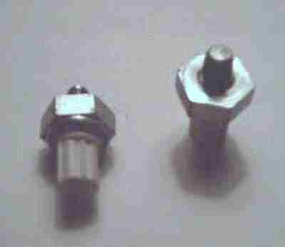
 The bolts are stretch-to-yield bolts which also makes them "use once" designs.
I've seen people reuse this types of bolts over again though. As long as you
don't stretch them past their stretch point they should be ok. They will be
replaced however with something stronger.
The bolts are stretch-to-yield bolts which also makes them "use once" designs.
I've seen people reuse this types of bolts over again though. As long as you
don't stretch them past their stretch point they should be ok. They will be
replaced however with something stronger.
These bolts aren't like most rod bolts either. Most rod bolts are pushed in
through the top of the rod and them the cap is put on and a nut is then used
to secure the cap. On these the cap is put onto the rod and the bolt is
screwed in from the cap side and the rod on top is threaded for the bolt.
Again, another race feature of the SHO V8.
 This is a picture of the shortblock, in my living room, with the oil pan off.
You can see how it's all crammed in there under the oil pan. The oil pick up,
the windage tray and the pickup for the oil pump which leads to the front of
the block.
This is a picture of the shortblock, in my living room, with the oil pan off.
You can see how it's all crammed in there under the oil pan. The oil pick up,
the windage tray and the pickup for the oil pump which leads to the front of
the block.
 The complete short block outside on the front porch. I put it there after I
disassembled it down to it's 175 pound weight. You can see how small this
engine really is. The deck is close to the main block. I think this is a
good design for strength. This motor almost seems bomb proof.
The complete short block outside on the front porch. I put it there after I
disassembled it down to it's 175 pound weight. You can see how small this
engine really is. The deck is close to the main block. I think this is a
good design for strength. This motor almost seems bomb proof.
 This is the short block from the back(driver's side) of the motor. You can
see all the webbing on the back and the thick flange of the rear of the crank.
The plug in the center top of the rear of the block is where the rear bearing
of the balance shaft is. The little tunnel on the bottom of the oil pan is
where the drain plug is.
This is the short block from the back(driver's side) of the motor. You can
see all the webbing on the back and the thick flange of the rear of the crank.
The plug in the center top of the rear of the block is where the rear bearing
of the balance shaft is. The little tunnel on the bottom of the oil pan is
where the drain plug is.
 Again, the shortblock. This is from the side. The long bolts on the bottom
of the left hand side of the picture are for the A/C compressor. You can see
the dishes in each of the pistons from the view and lighting. You can see the
oil serpator assembled. Removing it shows a small view of the balance shaft.
You can also see the knock sensors installed on either side of the oil
seperator.
Again, the shortblock. This is from the side. The long bolts on the bottom
of the left hand side of the picture are for the A/C compressor. You can see
the dishes in each of the pistons from the view and lighting. You can see the
oil serpator assembled. Removing it shows a small view of the balance shaft.
You can also see the knock sensors installed on either side of the oil
seperator.
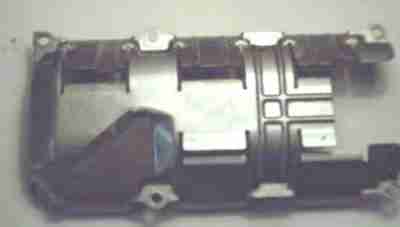
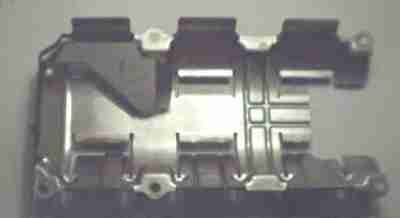
 Windage tray installed on the shortblock. This shows it attached without the
oil pump or pick up in the way. Oil falls over the crank and lands in the
tray. It then falls into the pan from the whole on the left.
Windage tray installed on the shortblock. This shows it attached without the
oil pump or pick up in the way. Oil falls over the crank and lands in the
tray. It then falls into the pan from the whole on the left.
The purpose of the windage tray is to keep oil from wrapping around the crank
and aerating the oil. This allows the crank to spin without the added drag of
the oil wrapping itself aroudn the crank. This adds a few HP. Also this is
something I won't need to get fabricated as I can use the stock one!
 Windage tray removed.
 Windage tray removed showing the inside.