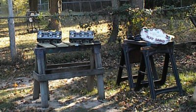
 Sandblasted, scrubbed with a toothbrush to remove any loose grit, thoroughly
rinsed, and drying. You have to get a fairly rough finish for the coatings to
stick properly.
Sandblasted, scrubbed with a toothbrush to remove any loose grit, thoroughly
rinsed, and drying. You have to get a fairly rough finish for the coatings to
stick properly.
Author: Dave Williams; dlwilliams=aristotle=net
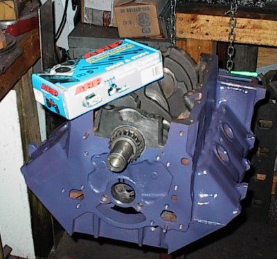
Bruce wanted something to replace the ailing 3.8 in the Black Car, his '86 Buick Grand National. We decided on a large bore 4.1L block and various goodies. Nothing spectacular.
For what was supposed to be just a high quality rebuild, I sure ran into a lot of problems with this one. Nothing wanted to fit without its due share of attention. More than once, I wound up throwing a bag over it and working on something else while deciding how to solve various problems.
Bruce and I decided we wanted the compression ratio to be 7.5:1, figured out the dish volume, specified the dishes be CNC-machined to match the Buick chambers, standard-width Chevy rings, slot type pin oilers, and everything else standard Buick 4.1, for a 4 inch bore. The specifications were faxed to BRC. These were very expensive pistons - $650 for six.
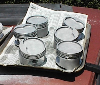
When the pistons came in, the first thing I noticed was that the pistons had big round bowls instead of the combustion-chamber-shaped dishes I'd specified. We called up BRC, FAX in hand, and their attitude was basically, "we have your money, you have the pistons, go away." One of the reasons for going to custom pistons was to take advantage of all the extra quench available with the large 4.1 bore. Now we didn't even have as much as a stock 3.8.
Next, I noticed that they had drilled pin oiler holes to the oil ring grooves. This is common enough, but the FAX specified slot type oilers, which are better for turbo motors. Then I noticed the pistons had .927" Chevrolet pins instead of .939" Buick pins. Another call to BRC, which didn't achieve any satisfaction either, but at least I could express my dissatisfaction again.
BRC is not only incompetent, they're a bunch of assholes too.
Later, as I was assembling the long block, I found out they'd also munged the valve reliefs. The Buick has four exhaust valves on the left, two on the right. I had six left-hand pistons. Not only that, the reliefs weren't in the right place - the valves hit the sides of the reliefs. After staring at things for a while, I realized they had machined the reliefs to clear the valves in Stage 1 heads, which have the valves closer to the chamber centerline than stock heads. I said to hell with it and adjusted the reliefs with the die grinder. It wasn't worth calling up the assholes at BRC to complain again.
Sandblasted, scrubbed with a toothbrush to remove any loose grit, thoroughly
rinsed, and drying. You have to get a fairly rough finish for the coatings to
stick properly.
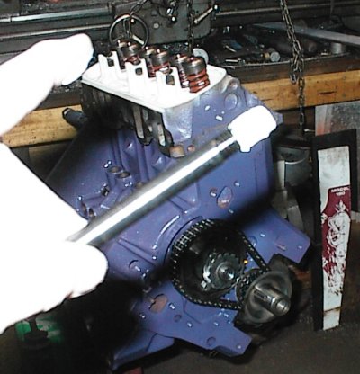
I didn't find out about the relief location problem until after they were coated, baked, polished, and hung on their rods.
Two pistons look like they have full-round dishes, but that's some weird
optical illusion. All six are the same.
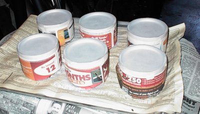 Here we are, masked and ready to put the ceramic thermal barrier on the tops.
 The tops have been ceramic'd, I'd just started on the moly coating on the
sides when my airbrush quit. Frantic fumbling didn't show anything wrong -
there's just a valve, a pot, and a nozzle - so I grabbed a foam brush that was
handy and used that. The brush gave a perfectly serviceable finish, but it
wasn't nearly as pretty as the airbrush gives.
The tops have been ceramic'd, I'd just started on the moly coating on the
sides when my airbrush quit. Frantic fumbling didn't show anything wrong -
there's just a valve, a pot, and a nozzle - so I grabbed a foam brush that was
handy and used that. The brush gave a perfectly serviceable finish, but it
wasn't nearly as pretty as the airbrush gives.
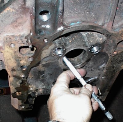
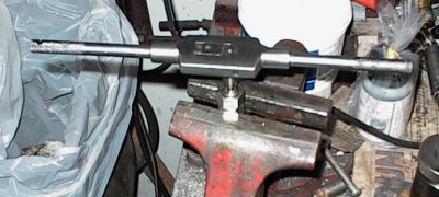
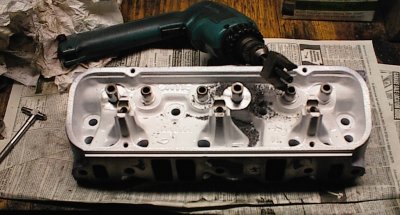
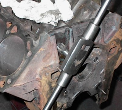 I've drilled the hole for the turbo oil return line, and now I'm tapping it.
It takes an amazing amount of force to turn a 1/2 NPT tap...
I've drilled the hole for the turbo oil return line, and now I'm tapping it.
It takes an amazing amount of force to turn a 1/2 NPT tap...
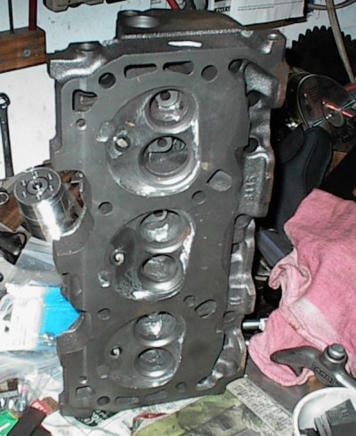
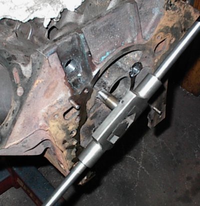 Tapping the oil galleries at the front of the block. The stock Buick has
push-in cup plugs here.
Tapping the oil galleries at the front of the block. The stock Buick has
push-in cup plugs here.
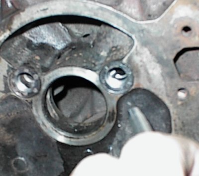
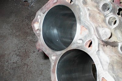
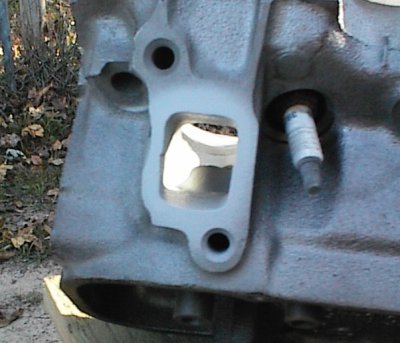
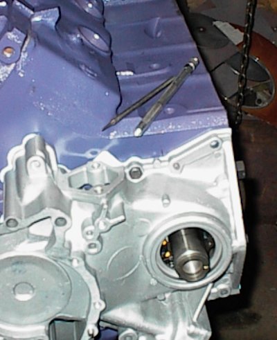
 This shot with the penlight shows how short the distance is from the front of
the block to the main oil gallery. You need a shorter than standard plug to
avoid restriction in the oil flow.
This shot with the penlight shows how short the distance is from the front of
the block to the main oil gallery. You need a shorter than standard plug to
avoid restriction in the oil flow.
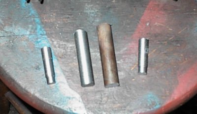
 The other side isn't that critical; it just feeds the lifters, the the passage
is further back. Ford 351 Cleveland rear lifter gallery plugs are an odd size
which worked nicely in this application.
The other side isn't that critical; it just feeds the lifters, the the passage
is further back. Ford 351 Cleveland rear lifter gallery plugs are an odd size
which worked nicely in this application.
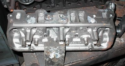
 Retapping all the head bolt holes so the new ARP studs will screw in properly.
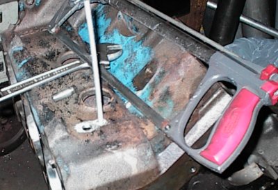
 Retapping the mains for the same reason. The tap handle wouldn't swing down
in the block, so I used Vise-Grips. It doesn't take a lot of force when
you're just cleaning up the threads.
Retapping the mains for the same reason. The tap handle wouldn't swing down
in the block, so I used Vise-Grips. It doesn't take a lot of force when
you're just cleaning up the threads.
Since it was very convenient to tune the engine by cylinder pressure on a continual basis, instead of just using the indicator to diagnose a problem, some enterprising Diesel guys reasoned that since pressure was what made it all work, you could measure pressure anywhere. One nifty and inexpensive device was a hole drilled through the cylinder wall, just before the exhaust valve opening point. The higher the average pressure, the higher the end pressure... and the end pressure was under 300 PSI. Since the hole was uncovered on the intake stroke as well, it measured average cylinder pressure, not peak... which was just fine. One of the methods of rating an engine's power output is by its cylinder pressure - Brake Mean Effective Pressure, or BMEP. To get more than 150 PSI BMEP requires some sort of supercharging and/or exotic fuels.
The end-pressure indicator consisted of the port in the block, a tube to a receiving chamber with a drain cock, and an ordinary dial pressure gauge. Sizing of the tubes, orifices, and receiving chamber volume would determine how stable the gauge reading was.
The fancy indicators, of course, could tell you the instantaneous pressure anywhere in the engine's cycle, which let you diagnose all kinds of injection problems easily. The end-pressure system only gives you mean, or average, pressure. It's not as useful for diagnostics, but it is still very useful for tuning.
For all practical purposes, BMEP is horsepower; the higher the BMEP, the higher the horsepower. Now, with this simple gauge system, we don't know the exact relationship between cylinder pressure and rear wheel horsepower... but it doesn't matter. In engineering, this is what a friend of mine calls "The Al Bundy Algorithm." This is commonly expressed as, "Don't know, don't care." We're tuning for maximum cylinder pressure; whatever maximum actually is doesn't matter, because maximum is all we can get.
Bruce decided he wanted a BMEP port, so I added one to the block. You can skip the next sequence of images if you don't care.
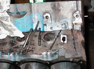 Drag out a bunch of drills and taps...
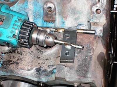
 Mark where to drill with a piece of tape, center punch, and drill a hole to
temporarily hold a drill fixture.
Mark where to drill with a piece of tape, center punch, and drill a hole to
temporarily hold a drill fixture.
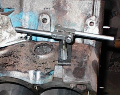
 Tap 5/16-18, bolt the drill jig down. It's just a piece of 3/8" steel scrap
with a couple of holes, but it's enough to keep all the drills and taps lined
up straight.
Tap 5/16-18, bolt the drill jig down. It's just a piece of 3/8" steel scrap
with a couple of holes, but it's enough to keep all the drills and taps lined
up straight.
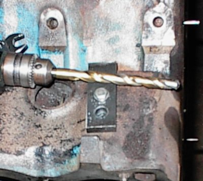
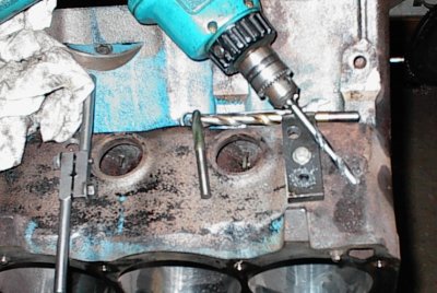 Next, we drill 5/16" through the outside of the water jacket.
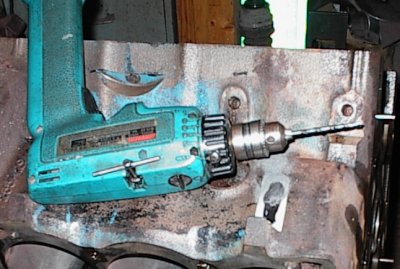
 Next, we chuck a 5/16" end mill into the drill, reach through the 5/16" hole,
and carefully machine a 5/16" flat into the outside of the cylinder wall.
Next, we chuck a 5/16" end mill into the drill, reach through the 5/16" hole,
and carefully machine a 5/16" flat into the outside of the cylinder wall.
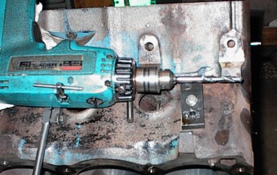
 Next we open the jig up to 27/64 on the drill press, bolt it back down on the
block, and open the outside hole up to 27/64, which is the correct tap drill
size for a 1/2-20 fine thread.
Next we open the jig up to 27/64 on the drill press, bolt it back down on the
block, and open the outside hole up to 27/64, which is the correct tap drill
size for a 1/2-20 fine thread.
 The jig is opened up to 1/2" on the drill press, reinstalled, and we tap 1/2"
for the bushing.
The jig is opened up to 1/2" on the drill press, reinstalled, and we tap 1/2"
for the bushing.
 All the drilling and tapping is done. Finally!
 The bushing is a piece of 1/2-20 stainless steel threaded rod. I drilled a
5/16" hole most of the way through on the lathe, taper reamed the opening,
tapped 1/8-27 NPT, flipped it around, and put a 5/16"x.060" nose on the closed
side. Here, I'm cleaning up the 1/8-27 threads. Cranking down a pair of nuts
lets me hold it in the vise without damaging any threads.
The bushing is a piece of 1/2-20 stainless steel threaded rod. I drilled a
5/16" hole most of the way through on the lathe, taper reamed the opening,
tapped 1/8-27 NPT, flipped it around, and put a 5/16"x.060" nose on the closed
side. Here, I'm cleaning up the 1/8-27 threads. Cranking down a pair of nuts
lets me hold it in the vise without damaging any threads.
 Now I've screwed a piece of threaded
rod into the temporary locating hole, and I'm getting ready to saw it off.
It's snug against the cylinder to provide a little extra support.
Now I've screwed a piece of threaded
rod into the temporary locating hole, and I'm getting ready to saw it off.
It's snug against the cylinder to provide a little extra support.
 The block has been ground down to fresh metal, the jig plug is cut off flush,
and a pipe plug has been inserted into the bushing to have something to turn
it in with, and to protect the threads. A dab of epoxy went on the closed end
of the bushing.
The block has been ground down to fresh metal, the jig plug is cut off flush,
and a pipe plug has been inserted into the bushing to have something to turn
it in with, and to protect the threads. A dab of epoxy went on the closed end
of the bushing.
At this point, the cylinder wall has a flat, but no hole, and the hole in the
bushing doesn't go all the way through either.
 Jumping ahead a bit, the bushing and plug have been welded, the welds dressed
with the grinder, and epoxy smeared around, just in case.
Jumping ahead a bit, the bushing and plug have been welded, the welds dressed
with the grinder, and epoxy smeared around, just in case.
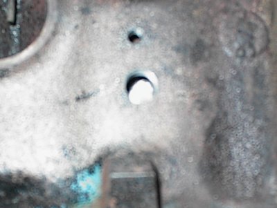
 Finally, I reached in through the bushing with a .087" drill bit and drilled
all the way through into the cylinder. I touched up the hole with a
countersink.
Finally, I reached in through the bushing with a .087" drill bit and drilled
all the way through into the cylinder. I touched up the hole with a
countersink.
It would have been best if the block hadn't been bored and honed yet, but it
worked out okay this way.
 There was a freeze plug rattling around inside the water jacket, left by a
previous rebuilder. I fought with it for an hour. My buddy Doug dropped by
and fished it out in about three minutes. Sometimes you feel like slapping
the sh*t out of someone, just because...
There was a freeze plug rattling around inside the water jacket, left by a
previous rebuilder. I fought with it for an hour. My buddy Doug dropped by
and fished it out in about three minutes. Sometimes you feel like slapping
the sh*t out of someone, just because...
 New brass plugs in the sides. The ones in the rear are already installed.
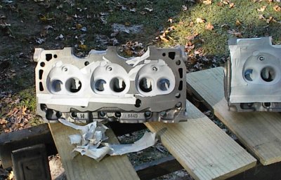
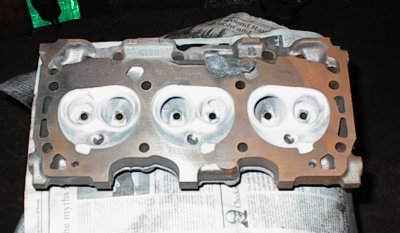
 Bruce had polished the combustion chambers and done some porting on the heads
before he brought them down. Pretty, aren't they?
Bruce had polished the combustion chambers and done some porting on the heads
before he brought them down. Pretty, aren't they?
 Not for long, as I get ready to fire up Mr. Sandblaster...
 The combustion chambers and exhaust ports got blasted to hold the thermal
barrier coating.
The combustion chambers and exhaust ports got blasted to hold the thermal
barrier coating.
 The Buick V6s have a bunch of passages drilled from the exhaust port bowls,
across the width of the head, and through the manifold face. On carbureted
engines, two of these passages are used for the exhaust crossover under the
intake. For injected cars, only one port is connected to the intake, for EGR.
All the rest are blocked by the gasket.
The Buick V6s have a bunch of passages drilled from the exhaust port bowls,
across the width of the head, and through the manifold face. On carbureted
engines, two of these passages are used for the exhaust crossover under the
intake. For injected cars, only one port is connected to the intake, for EGR.
All the rest are blocked by the gasket.
After much head scratching and belly-button inspecting, we decided the maze of
drillings was intended to speed engine warm-up for emissions purposes. We
certainly didn't need to put any more heat into the water jacket with this
particular engine, so I machined a bunch of plugs on the lathe to block off
all the holes, since Bruce isn't using EGR. Some of the holes were stepped,
so the plugs could be simply driven in with epoxy; the large ones in the
middle intersected, so I beveled one plug, which was retained by the one that
passed it.
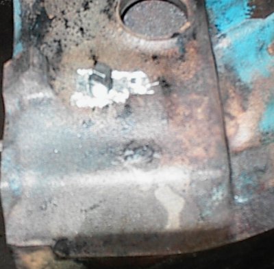
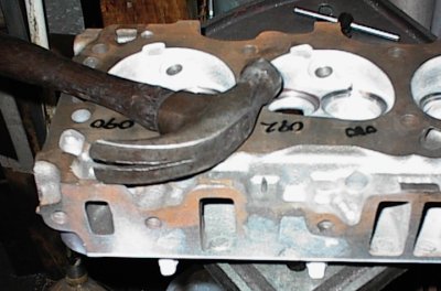
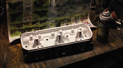
 Here, I've welded the intake faces there the plugs were driven in, slopped
some epoxy in to neaten things up, and I have this head propped so the epoxy
won't drool away before it sets up.
Here, I've welded the intake faces there the plugs were driven in, slopped
some epoxy in to neaten things up, and I have this head propped so the epoxy
won't drool away before it sets up.
 Remember that one plug that slid right in? It's epoxied along its length and
welded at the manifold end, but paranoia is your friend. I'm drilling a hole
for a roll pin, just for general belt-and-suspenders-ness.
Remember that one plug that slid right in? It's epoxied along its length and
welded at the manifold end, but paranoia is your friend. I'm drilling a hole
for a roll pin, just for general belt-and-suspenders-ness.
 Roll pin installed. I ground it off flush, staked it, and then covered the
area with epoxy. Yes, I am paranoid. Why do you ask?
Roll pin installed. I ground it off flush, staked it, and then covered the
area with epoxy. Yes, I am paranoid. Why do you ask?
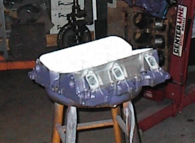
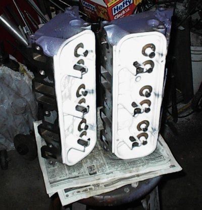
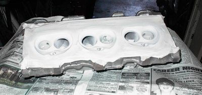 Here we are, all coated...
 And detaping...
I baked them in the oven in the house; the ceramic
doesn't outgas anything noxious.
 Polishing the combustion chambers and ports with 0000 steel wool. The ceramic
shines up bright silver after the surface film is scrubbed away.
Polishing the combustion chambers and ports with 0000 steel wool. The ceramic
shines up bright silver after the surface film is scrubbed away.
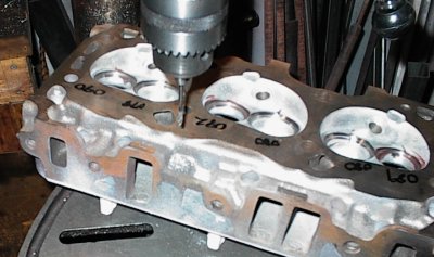
 Now I'm cutting new valve seats. The ceramic and resin tend to gum up the
stones, so they have to be sharpened after every seat. The stock valve guides
were in fine shape, astonishingly enough!
Now I'm cutting new valve seats. The ceramic and resin tend to gum up the
stones, so they have to be sharpened after every seat. The stock valve guides
were in fine shape, astonishingly enough!
 Standard three-angle valve job. The numbers in felt tip are the seat widths.
I cut the exhaust seats wider than usual to help transfer heat from the
exhaust valve to the head. Every little bit helps when you're trying to avoid
detonation. On the flow bench a narrower seat will usually pass more air, but
my view is that temperature management is more important on a turbo motor.
Standard three-angle valve job. The numbers in felt tip are the seat widths.
I cut the exhaust seats wider than usual to help transfer heat from the
exhaust valve to the head. Every little bit helps when you're trying to avoid
detonation. On the flow bench a narrower seat will usually pass more air, but
my view is that temperature management is more important on a turbo motor.
 Mask off the guides and shaft mounts, and paint with white epoxy.
 First coat of paint on the outside next...
 Somehow, the combination of stock Buick valves, Chevy springs, and Chevy
titanium retainers wound up substantially short on spring installed height.
So I cut the valve seats down with this special cutter until everything was
correct. This is very rare; normally, you wind up shimming the springs, not
cutting the seats!
Somehow, the combination of stock Buick valves, Chevy springs, and Chevy
titanium retainers wound up substantially short on spring installed height.
So I cut the valve seats down with this special cutter until everything was
correct. This is very rare; normally, you wind up shimming the springs, not
cutting the seats!
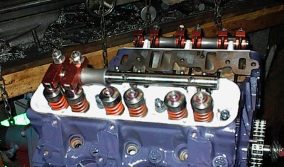
 Setting up to check the rocker geometry. The roller rockers contacted the
valve stems just off center. They were within the useable range, but since we
were buying new pushrods anyway, shorter to compensate for the hydraulic
roller lifters, tried adjusting the pushrod length to center the wipe
patterns. After much experimentation, I finally realized that the pushrod
length doesn't do squat when you have shaft mounted rockers.
Setting up to check the rocker geometry. The roller rockers contacted the
valve stems just off center. They were within the useable range, but since we
were buying new pushrods anyway, shorter to compensate for the hydraulic
roller lifters, tried adjusting the pushrod length to center the wipe
patterns. After much experimentation, I finally realized that the pushrod
length doesn't do squat when you have shaft mounted rockers.
Well, DUH [sigh]
 Plenty of room for the valves vertically, but we have side contact.
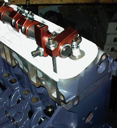 Just another shot of the test setup.
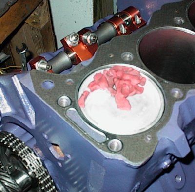
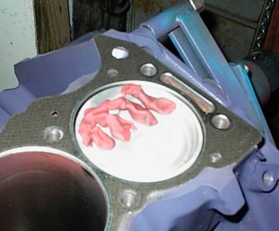 I clayed each piston in turn, until I realized the left/right hand problem and
the BRC piston screwup. A little work with Mr. Die Grinder, and we're back
in business. It would have been neater to fixture them in the milling
machine, but the grinder works fine and is much faster.
I clayed each piston in turn, until I realized the left/right hand problem and
the BRC piston screwup. A little work with Mr. Die Grinder, and we're back
in business. It would have been neater to fixture them in the milling
machine, but the grinder works fine and is much faster.
 Now we've cut the spring seats, ground the sides of the stands to clear the
rockers, and trimmed the guide length. And cleaned, dried, and oiled the
heads for the dozenth time...
Now we've cut the spring seats, ground the sides of the stands to clear the
rockers, and trimmed the guide length. And cleaned, dried, and oiled the
heads for the dozenth time...
 After assembling the heads and bolting them down on the gaskets, I found that
the rockers didn't line up with the valve stems, and the center bolt wouldn't
go into its pedestal. The spacers were two different lengths, and the hole in
the shaft was very slightly offset, as were the pedestals. The rocker shafts
had been assembled backwards. Swapping them side for side didn't work, so I
disassembled them, swapped all the bits around, and put them back together.
Everything was fine, then.
After assembling the heads and bolting them down on the gaskets, I found that
the rockers didn't line up with the valve stems, and the center bolt wouldn't
go into its pedestal. The spacers were two different lengths, and the hole in
the shaft was very slightly offset, as were the pedestals. The rocker shafts
had been assembled backwards. Swapping them side for side didn't work, so I
disassembled them, swapped all the bits around, and put them back together.
Everything was fine, then.
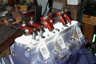
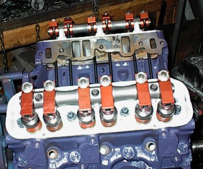 Here we are, finally. The two rockers on the right line up correctly, it's
just parallax error from the camera. The pushrods are custom-length Howards
5/16" chrome moly.
Here we are, finally. The two rockers on the right line up correctly, it's
just parallax error from the camera. The pushrods are custom-length Howards
5/16" chrome moly.
Nice color scheme, eh?
 While setting the valves, I found two adjustors took a lot more travel than the
others, and both those valves were in coil bind. This was another "put a bag
over it and think about it for a while" thing. I made up a list of things to
check. I kept having visions of eating a $150 pair of head gaskets to fix
something.
While setting the valves, I found two adjustors took a lot more travel than the
others, and both those valves were in coil bind. This was another "put a bag
over it and think about it for a while" thing. I made up a list of things to
check. I kept having visions of eating a $150 pair of head gaskets to fix
something.
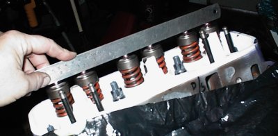
Here, I'm verifying that all the valves are the same height.
 Next, I checked the lift on each lobe and the height of each spring retainer,
using a solid lifter I moved from hole to hole, and wrote all the results down
on a notepad. All those were correct, too.
Next, I checked the lift on each lobe and the height of each spring retainer,
using a solid lifter I moved from hole to hole, and wrote all the results down
on a notepad. All those were correct, too.
To make a long story short, it turned out to be some bad lifters. The Competition Cams link-bar hydraulic roller lifters have a very long travel - .230"! - and two of them were completely collapsed and wouldn't spring back. Another one was sticky. Bad lifters, okay. Bruce called the vendor he ordered them from, and got them to send some replacements by Federal Express. Meanwhile, I dropped in to talk to John at Motor Pro, a local shop, to see if by any chance he had any lifters like that on hand. He didn't, but he'd seen the problem before. Some roller lifters come packed with a waxy lubricant that gums up and keeps them from working properly. Since the link bars were riveted to the lifter bodies we couldn't get them apart, but soaking them in carburetor cleaner freed them up. Thanks, John!
Now, you might wonder what a collapsed lifter has to do with coil bind. That's due to the peculiarity of the adjustable rockers on shafts - when you run the screw down, it moves the cup down, which changes the rocker motion curve slightly. With the collapsed lifters set to zero lash, we had just enough extra lift to bind the springs.
Yes, it's very strange...
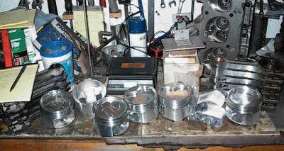 Balancing the pistons. No, the workbench never seems to get much cleaner than
this...
Balancing the pistons. No, the workbench never seems to get much cleaner than
this...
 Balancing the rods. You can see the polished shanks good in this picture.
What the heck, it can't hurt, considering 30 pounds of boost...
Balancing the rods. You can see the polished shanks good in this picture.
What the heck, it can't hurt, considering 30 pounds of boost...
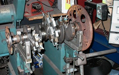 Balancing the crank. The BRCs were a bit heavier than the stock pistons, so
it took a little lead at each end. I'm using the stock 36.6% balance factor.
Balancing the crank. The BRCs were a bit heavier than the stock pistons, so
it took a little lead at each end. I'm using the stock 36.6% balance factor.
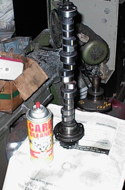 Cast steel hydraulic roller cam. I'm hosing off the corrosion inhibitor gunk
with carb cleaner.
Cast steel hydraulic roller cam. I'm hosing off the corrosion inhibitor gunk
with carb cleaner.
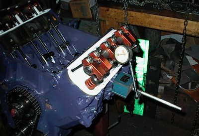
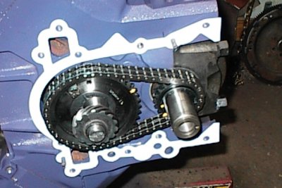
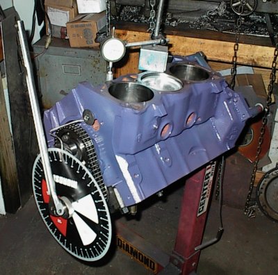 Now we degree the cam. The cam measured 109.5 degrees on a 110 specified
intake lobe center. This is dead nuts in the Real World(tm).
It's not unusual to find cams several degrees off from their stated
centerline.
Now we degree the cam. The cam measured 109.5 degrees on a 110 specified
intake lobe center. This is dead nuts in the Real World(tm).
It's not unusual to find cams several degrees off from their stated
centerline.
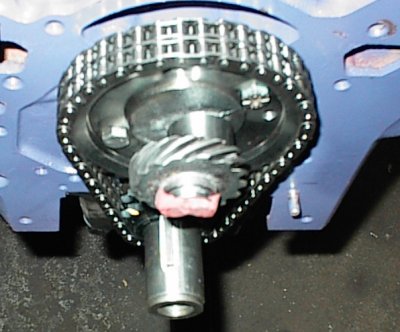
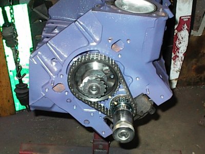 The instructions for the Edelbrock timing set didn't say anything about the
cam tensioner. Most roller chain sets for the Buick discard the tensioner, but
I felt there was too much slack in the chain without it.
The instructions for the Edelbrock timing set didn't say anything about the
cam tensioner. Most roller chain sets for the Buick discard the tensioner, but
I felt there was too much slack in the chain without it.
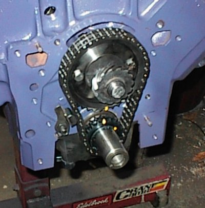 The local GM dealer didn't have a replacement rubbing block in stock, so I
refaced the old one with the belt sander and installed it. Getting that
little spring into the hole in the block is a bugger. A rivet in the back of
the rubbing block keeps the spring from sliding out. It looks very mickey
mouse, but it seems to work okay in practice.
The local GM dealer didn't have a replacement rubbing block in stock, so I
refaced the old one with the belt sander and installed it. Getting that
little spring into the hole in the block is a bugger. A rivet in the back of
the rubbing block keeps the spring from sliding out. It looks very mickey
mouse, but it seems to work okay in practice.
 Competition Cams roller thrust button. Slap some clay on the end to check the
timing cover clearance...
Competition Cams roller thrust button. Slap some clay on the end to check the
timing cover clearance...
 Install the gasket so everything stacks up right...
 Temporarily install the cover...
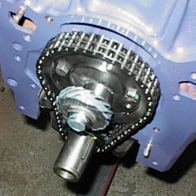 ...and find we have negative clearance, even without any of the shims Comp
provided with the roller bearing kit. I wound up using the belt sander on the
end of the button until I got the clearance right, then hosed it out with
carb cleaner to get the grit out.
...and find we have negative clearance, even without any of the shims Comp
provided with the roller bearing kit. I wound up using the belt sander on the
end of the button until I got the clearance right, then hosed it out with
carb cleaner to get the grit out.
I don't know if the thrust button was overlong to start with, or if it was a
problem with the aftermarket timing cover, or both, but it was no big deal.
 Final check. I reached in through the fuel pump port with the dental pick to
make sure the button turned freely. I don't know exactly what the clearance
is, since it's hard to measure less than .010" with clay, but as long as it
turns freely it won't bind against the cover, which is all that matters.
Final check. I reached in through the fuel pump port with the dental pick to
make sure the button turned freely. I don't know exactly what the clearance
is, since it's hard to measure less than .010" with clay, but as long as it
turns freely it won't bind against the cover, which is all that matters.
 The Grand National engines use a baffled pan. The 4.1 has a different oil pan
bolt pattern, and none of the 4.1s ever had a baffle. I made one out of sheet
metal. Here, I'm making the pattern out of poster board.
The Grand National engines use a baffled pan. The 4.1 has a different oil pan
bolt pattern, and none of the 4.1s ever had a baffle. I made one out of sheet
metal. Here, I'm making the pattern out of poster board.
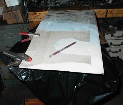 Now I've laid the poster board pattern onto the sheet metal...
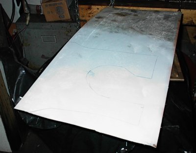 ...and traced out the lines.
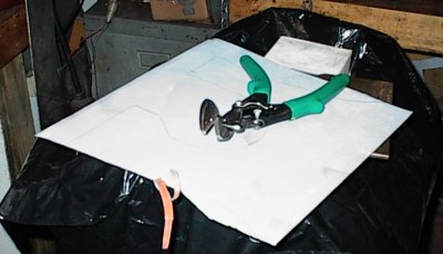 A little tin snip work is easy.
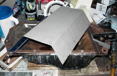
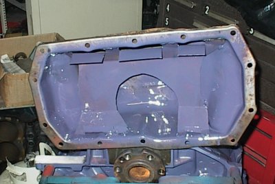 Baffle welded in place, pan scrubbed with a wire brush to remove MIG spatter,
and first coat of paint. The flanges on the top direct oil slung off the
crank down to the sump. The flanges at the bottom are supposed to catch oil
coming off the other side. The large hole was necessary to clear the pickup
tube; I still have to tilt the pan at an odd angle to get it around the pickup
and down on the block.
Baffle welded in place, pan scrubbed with a wire brush to remove MIG spatter,
and first coat of paint. The flanges on the top direct oil slung off the
crank down to the sump. The flanges at the bottom are supposed to catch oil
coming off the other side. The large hole was necessary to clear the pickup
tube; I still have to tilt the pan at an odd angle to get it around the pickup
and down on the block.
 Blue Loctite 242 on the pickup tube bolts. There's a paper gasket between the
tube and the block.
Blue Loctite 242 on the pickup tube bolts. There's a paper gasket between the
tube and the block.
 Bruce had found out that the turbo six responded well to increased intake
manifold volume. We figured that we could close off the underside of the
stock intake, which has a small plenum up on stiltlike runners.
Bruce had found out that the turbo six responded well to increased intake
manifold volume. We figured that we could close off the underside of the
stock intake, which has a small plenum up on stiltlike runners.
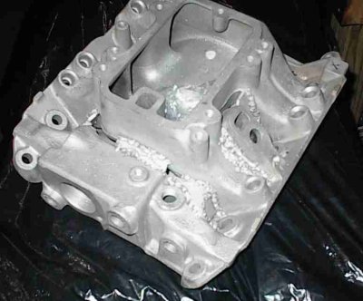
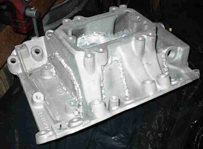 I cut little pieces of .125" aluminum to block off the cracks. Here, I'm just
getting started. My MIG welder didn't penetrate worth a flip, so I shipped
the intake and the rest of the blockoff bits to Bruce, who took it to someone
with a TIG welder to have it finished up. That guy said it was a pain to
weld, so I didn't feel so bad. Sometimes some aluminum alloys aren't real
compatible to the welding process.
I cut little pieces of .125" aluminum to block off the cracks. Here, I'm just
getting started. My MIG welder didn't penetrate worth a flip, so I shipped
the intake and the rest of the blockoff bits to Bruce, who took it to someone
with a TIG welder to have it finished up. That guy said it was a pain to
weld, so I didn't feel so bad. Sometimes some aluminum alloys aren't real
compatible to the welding process.
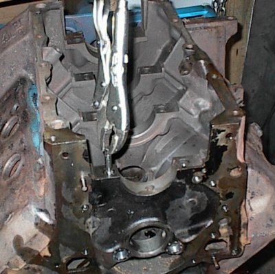
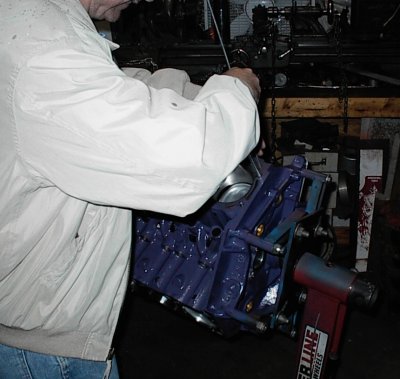
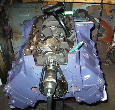
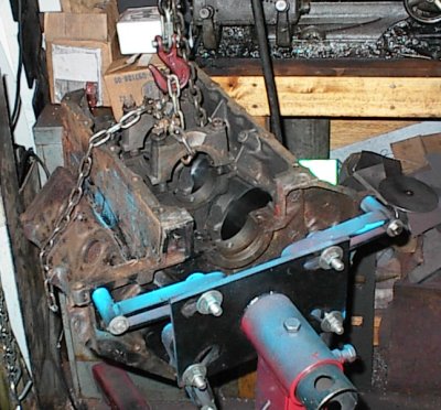 Here we go. It's been eight or nine months since I first started, seven
months since the block was honed, ten minutes since I got started on the final
assembly. Step 1: put it on an engine stand.
Here we go. It's been eight or nine months since I first started, seven
months since the block was honed, ten minutes since I got started on the final
assembly. Step 1: put it on an engine stand.
 Now we will scrape the decks clean, then carefully sandpaper as necessary,
while being careful not to create low spots. Every major gasket maker goes
into hysterics if you use Scotchbrite cookies on power tools; they are
aggressive enough to cause low spots that will cause sealing problems.
Now we will scrape the decks clean, then carefully sandpaper as necessary,
while being careful not to create low spots. Every major gasket maker goes
into hysterics if you use Scotchbrite cookies on power tools; they are
aggressive enough to cause low spots that will cause sealing problems.
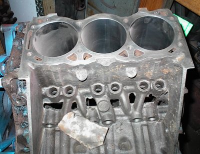
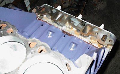
 This engine had been rebuilt before, and they apparently got a little wild
with something rotary. One corner had some fairly deep scratches. Not enough
to justify decking the block, but enough to be annoying. The scratches are in
the left corner, obscured by the flash. Well, I guess they weren't
that bad if the camera didn't pick them up.
This engine had been rebuilt before, and they apparently got a little wild
with something rotary. One corner had some fairly deep scratches. Not enough
to justify decking the block, but enough to be annoying. The scratches are in
the left corner, obscured by the flash. Well, I guess they weren't
that bad if the camera didn't pick them up.
 Zipping along past many hours of cleaning and painting...
Balanced, polished, cleaned crank, at home with new main bearings, caps
installed. Now for the new ARP main studs...
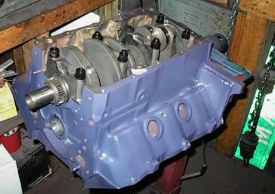 Studs installed. For some reason, some of them were longer than others.
The catalog and instructions said nothing; perhaps the Stage I blocks took
different lengths. I've come to find out almost all the stuff for a Buick
assumes Stage parts instead of stock stuff. I put the short studs at the ends
so they wouldn't interfere with the oil pan.
Studs installed. For some reason, some of them were longer than others.
The catalog and instructions said nothing; perhaps the Stage I blocks took
different lengths. I've come to find out almost all the stuff for a Buick
assumes Stage parts instead of stock stuff. I put the short studs at the ends
so they wouldn't interfere with the oil pan.
 Ring squaring tool for gapping the rings...
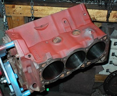
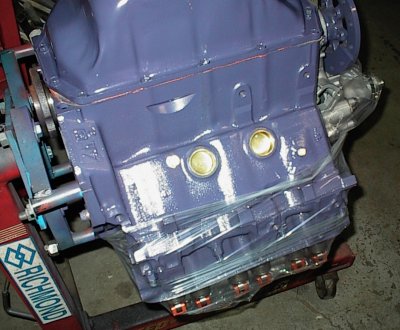
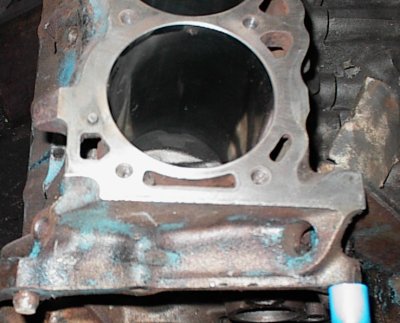
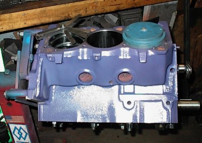
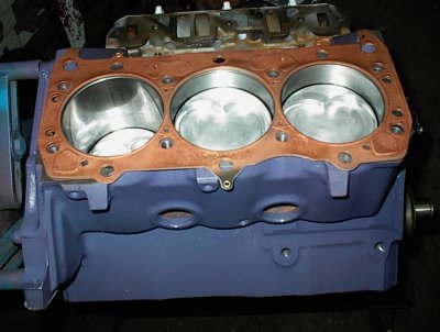
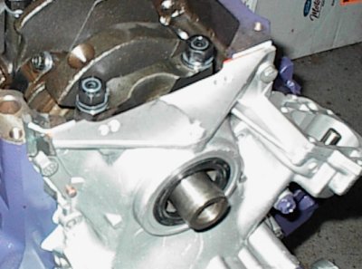
You can see the 1/4 NPT tapped hole I added in the water jacket for a drain
plug. Buick didn't provide any, for some reason. This side's plug is well
forward so you can get to it with the starter in place.
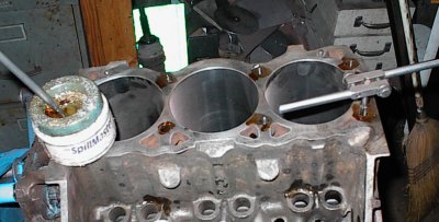
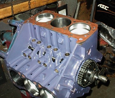
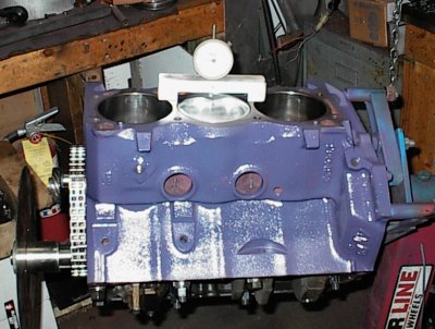 Voila! All the pistons are in, and now we're checking the stack height in
each hole.
Voila! All the pistons are in, and now we're checking the stack height in
each hole.
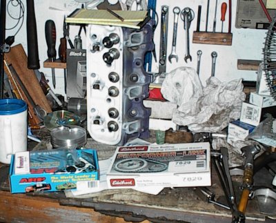 Just an "in process" shot of the bench. As usual, a glass of iced tea and at
least one notepad for keeping track of all the details.
Just an "in process" shot of the bench. As usual, a glass of iced tea and at
least one notepad for keeping track of all the details.
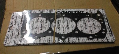 Cometic three-layer metal head gaskets. They're supposed to be the bling-
bling for high boost turbo engines.
Cometic three-layer metal head gaskets. They're supposed to be the bling-
bling for high boost turbo engines.
These critters cost $150 per pair.
 The three layers are riveted together with tabs outside the clamping area.
 The Stage II engines had six bolts per cylinder, so there are extra bolt holes
we won't be using. The gaskets had embossed areas that looked like they might
be intended to seal various water holes, but they didn't line up with anything
in particular. It didn't look like they would hurt anything, though. Perhaps
more Stage stuff.
The Stage II engines had six bolts per cylinder, so there are extra bolt holes
we won't be using. The gaskets had embossed areas that looked like they might
be intended to seal various water holes, but they didn't line up with anything
in particular. It didn't look like they would hurt anything, though. Perhaps
more Stage stuff.
 The gaskets had a very thin plastic coating. I wasn't particularly confident
they would properly seal the coolant passages, so I sprayed them with KW
Kopper-Kote gasket sealer.
The gaskets had a very thin plastic coating. I wasn't particularly confident
they would properly seal the coolant passages, so I sprayed them with KW
Kopper-Kote gasket sealer.
Note the reflections from the cylinder walls; moly rings require a very smooth
finish, unlike the cross-hatch you needed with old-style chrome rings.
 Lots of flash flare in this shot; just showing Teflon sealer applied to the
ARP head stud. If you don't use sealer there's a chance water can seep up
around the threads and get into the oil. And when you clean the threads with
a tap like ARP recommends, that chance approaches certainty.
Lots of flash flare in this shot; just showing Teflon sealer applied to the
ARP head stud. If you don't use sealer there's a chance water can seep up
around the threads and get into the oil. And when you clean the threads with
a tap like ARP recommends, that chance approaches certainty.
 Much-modified heads sitting down on their expensive head gaskets. Finally it
becomes a long block!
Much-modified heads sitting down on their expensive head gaskets. Finally it
becomes a long block!
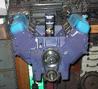 Spare pair of stock valve covers keeps overspray off the white paint on the
heads. And the Z-28 springs, and the titanium retainers, and... the spray
can says "Dupli-Color Plum Purple." Bruce wanted black. I told him it was
just a sort of purplish shade of black...
Spare pair of stock valve covers keeps overspray off the white paint on the
heads. And the Z-28 springs, and the titanium retainers, and... the spray
can says "Dupli-Color Plum Purple." Bruce wanted black. I told him it was
just a sort of purplish shade of black...
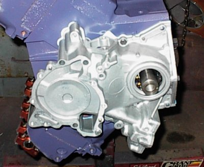
 The aftermarket timing cover has a deep pocket for the oil pump gears, to take
longer, high volume gears. It also came drilled for both the early and late
Buick oil pan bolt patterns.
The aftermarket timing cover has a deep pocket for the oil pump gears, to take
longer, high volume gears. It also came drilled for both the early and late
Buick oil pan bolt patterns.
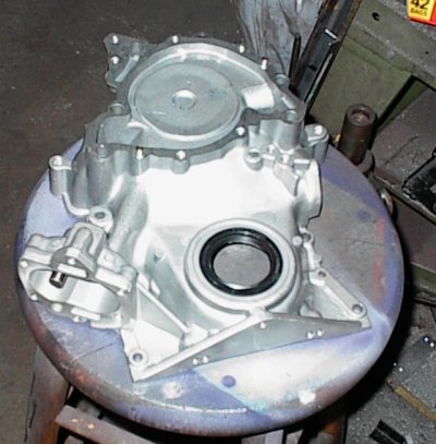 The cover also came with a rubber seal, which I've just installed, and a whole
assortment of springs to set the oil pressure. Not a bad part!
The cover also came with a rubber seal, which I've just installed, and a whole
assortment of springs to set the oil pressure. Not a bad part!
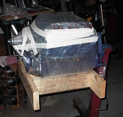 Ta-daa! A simple wooden carrier to keep it from rolling around in the back of
Bruce's truck, plastic to keep the grunge out.
Ta-daa! A simple wooden carrier to keep it from rolling around in the back of
Bruce's truck, plastic to keep the grunge out.
M A X I M U M O V E R D R I V E R A C I N G E N G I N E S
4.1 Buick V6 for Bruce Plecan, Arcanum OH
completed 12/03/03 (long block)
4.00 bore
3.40 stroke
256 CID, 4202cc (4.2L)
700 4.0 x 3.4
8.24 stock 4.1 composition gasket
48 stock chamber size
35 piston dish volume
------
791.24 cc total volume
8.24 stock 4.1 composition gasket
48 chamber size
35 dish volume
------
91.24 cc clearance volume
791.24 / 91.24 = 8.67:1 CR
warranty: if it breaks, you get to keep all the pieces you can find
COMPONENTS ---------------------------------------------------------------
Block:
4.1 block
4.000 bore
new cam bearings (had to scape #1 for clearance), Dura-Bond F-30
drilled and tapped for water drains
installed 1/8 NPT bushing for cylinder pressure measurement
chased all threaded holes
Rust-Oleum red primer, Dupli-Color Plum Purple engine paint
ARP main studs
rubber rear main seal
rubber front seal
ARP head studs, ARP and Mr. Gasket washers (studs too long)
studs set in Teflon sealer
mains STD uppers, .001 lowers, King MB-443-AM
Oiling:
4.1 oil pan
new 4.1 pickup tube
drilled oil passages larger
custom tray/scraper/baffle welded into pan
large neodymium magnet in pan by drain plug
new timing cover with built-in HV pump, PN 6571HI
offset #2,3,4 cam bearings, new .090 oil holes
Crankshaft:
stock 4.1 crank, undercut fillets
not turned; polished journals
balanced with 4.1 damper, flexplate
main journals:
#1 2.4990"
#2 2.4987"
#3 2.4987"
#4 2.4987"
Connecting Rods:
stock rods
polished shanks
ARP 7/16" rod bolts, 123-6002, 1.7" U.H.L.
balanced
bronze bushed for Chevy pins
single .125 oil hole at top of pin end
standard size bearings, King CR-6616-AM
Pistons:
BRC custom forgings
35cc round dish
5/32, 5/32, 7/32 standard Chevy ring width
CBC-2 ceramic thermal barrier coated tops
TLML moly antifriction coated sides
dual Spirolox pin retention
pin oiling via drilled passages to oil rings
2.5" taper wall pins .927" dia.
pistons are 6 LH exhaust instead of 4 LH, 2 RH; Stage II valve
positions
hand-cut valve notches to clear std. exhaust valves, .080+"
~.200 valve vertical clearance, all valves
Stack Height:
#1) -.024" #2) -.021"
#3) -.022" #4) -.025"
#5) -.025" #6) -.027"
Rings:
Hastings moly rings, 4.000 nominal bore, 5/32, 5/32, 7/32
#1 .020" #2 .022"
.015" .016"
.022/.022" .027/.027"
#3 .020" #4 .020"
.017" .016"
.023/.023" .023/.023"
#5 .020" .020"
.016" .014"
.025/.023" .023/.023"
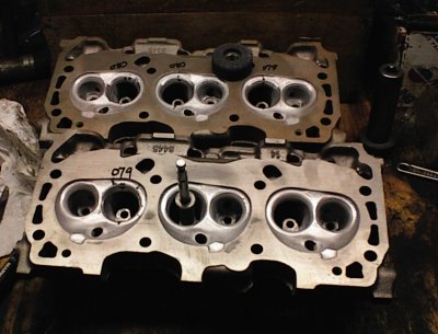
Cylinder Heads:
#445 casting cylinder heads
48cc chambers (stock)
coated chambers, exhaust ports, valves CBC-2 thermal barrier
stock integral iron valve guides (OK)
blocked heat passages in heads with steel dowels, welded and pinned
decked flat
all threaded holes chased
recut guides to .640 intake, .790 exhaust, for retainer/seal clrc.
nylon unbrellas on intake valves
Olds hard nylon umbrella seals on intake side, .110 thick, .090" lift
clearance
no seals on exhaust side, .090" lift clearance
Chevy steel umbrellas
Mobil 1 grease around keepers for oil control
narrowed pedestals to clear roller rocker bodies
springs installed at 1.71 nominal; cut seats down for spring height
standard valve keepers
Chevy Z-28 valve springs, Competition Products, good to .510 lift
Chevy titanium retainers, 1.25" diameter
.070" intake seats
.090" exhaust seats
spring and lift measurements, on assembled long block:
cyl. vlv. closed open v.lift spring (between coils)
#1 E 1.82 1.32 .500 .028
I 1.81 1.31 .500 .028
#3 I 1.82 1.31 .510 .030
E 1.80 1.29 .510 .030
#5 I 1.81 1.30 .510 .018 (crooked coils)
E 1.80 1.305 .495 .026
#2 E 1.76 1.26 .500 .028
I 1.77 1.27 .500 .030
#4 I 1.81 1.31 .500 .030
E 1.81 1.31 .500 .030
#6 I 1.80 1.30 .500 .018 (crooked coils)
E 1.81 1.31 .500 .030
Cam Specification:
Comp Cams BV69 258 HR 10 grind
Serial No UE7146
Intake Ex
Valve Adj Hyd Hyd
Gross Lift .496 .496
Dur@ 006 258 258
Valve Timing Open Close
at .050 In 7- BTDC 33 ABDC
Ex 33 BBDC 7- ATDC
at 110 degrees intake center line
Dur at .050 In, 206 Ex, 206
Lobe lifts .320
Lobe separation 110 degrees
Valvetrain:
cast hydraulic roller cam
Comp Cams Chevrolet hydraulic roller lifters, link bar type
.230 lifter travel
preloaded 3/4 turn
Edelbrock roller timing chain
stock cam chain tensioner
cam degreed in at 109.5
Comp Cams roller thrust button, PN 269, ~.005" clearance
drill .090" holes in #2, 3, 4 cam bearings, index to restrict oil flow
left #1 cam bearing alone
had to scrape front cam bearing for cam to turn
5/16" pushrods, length 8.25"; Howards Cams customs, PN PO209503
T&D shaft mount roller rockers, 1.6:1
Torque:
ARP main studs, 7/16", with ARP moly lube: 70 ft-lb
ARP rod bolts, 123-6002, with ARP moly lube: 50 ft-lb
ARP head studs, 1/2", with ARP moly lube: 90 ft-lb
Miscellaneous:
turning torque 15-20 ft-lb, cam but no valvetrain
new water pump
head studs too long; 4 studs 1/2" too long, used 4 bolts on
passenger outboard
used Mr. Gasket washers stacked on ARP washers
Cometic multi layer metal head gaskets, H1603SP1045QS. .045 thick
used KW Copper-Kote on gaskets