Like most people who've started something like this have mentioned, the major part of time is in the brackets and details. It took longer to make the A- arms than it did to make the chassis! Just about everything has gone that way.
Not a whole lot of images yet; about half of them are still on 35mm film, waiting to be developed and scanned. I like my new digital camera!
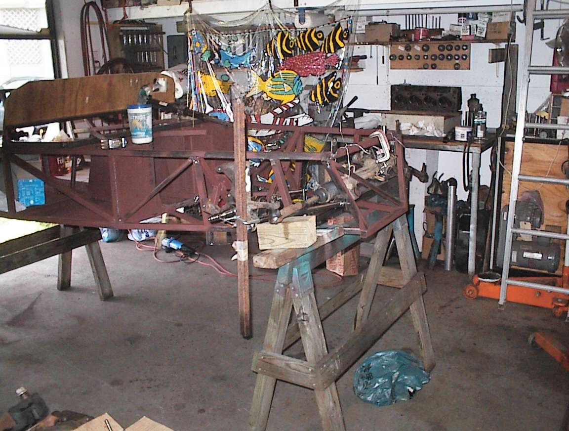
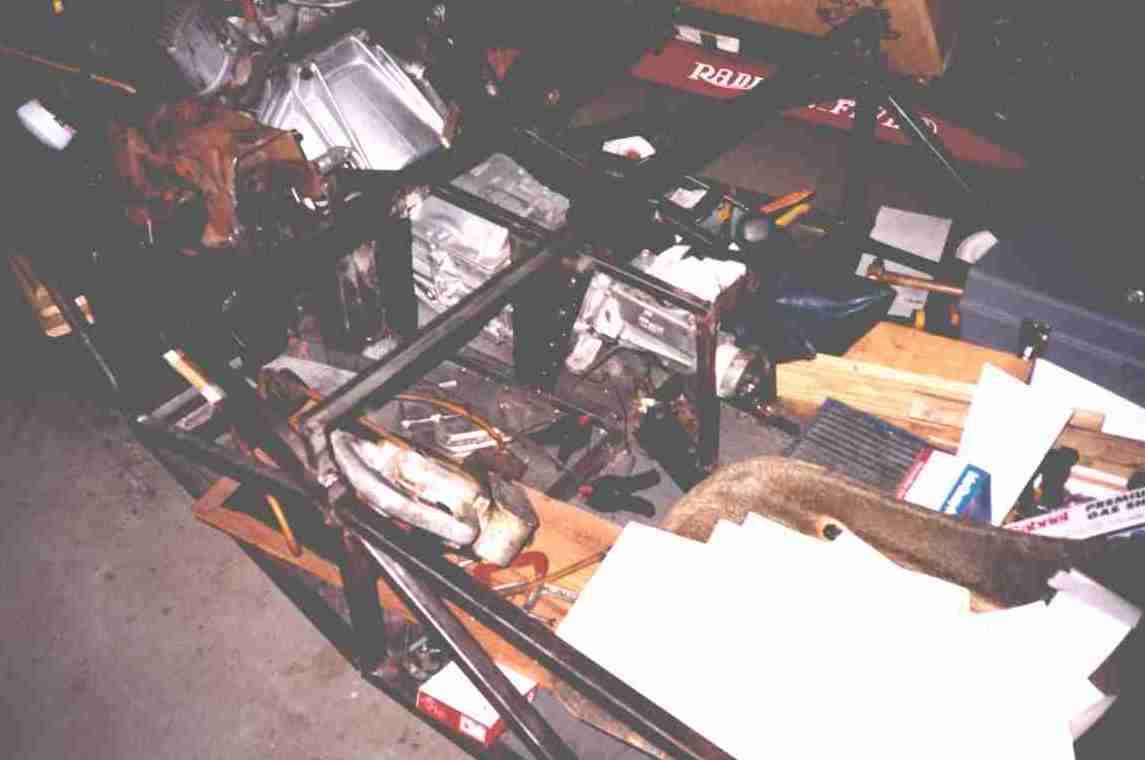 Mocking more stuff up. The chassis provides a convenient catch-all for
construction debris. The center spine is now wrapped around the transmission
as best as we can do.
Mocking more stuff up. The chassis provides a convenient catch-all for
construction debris. The center spine is now wrapped around the transmission
as best as we can do.
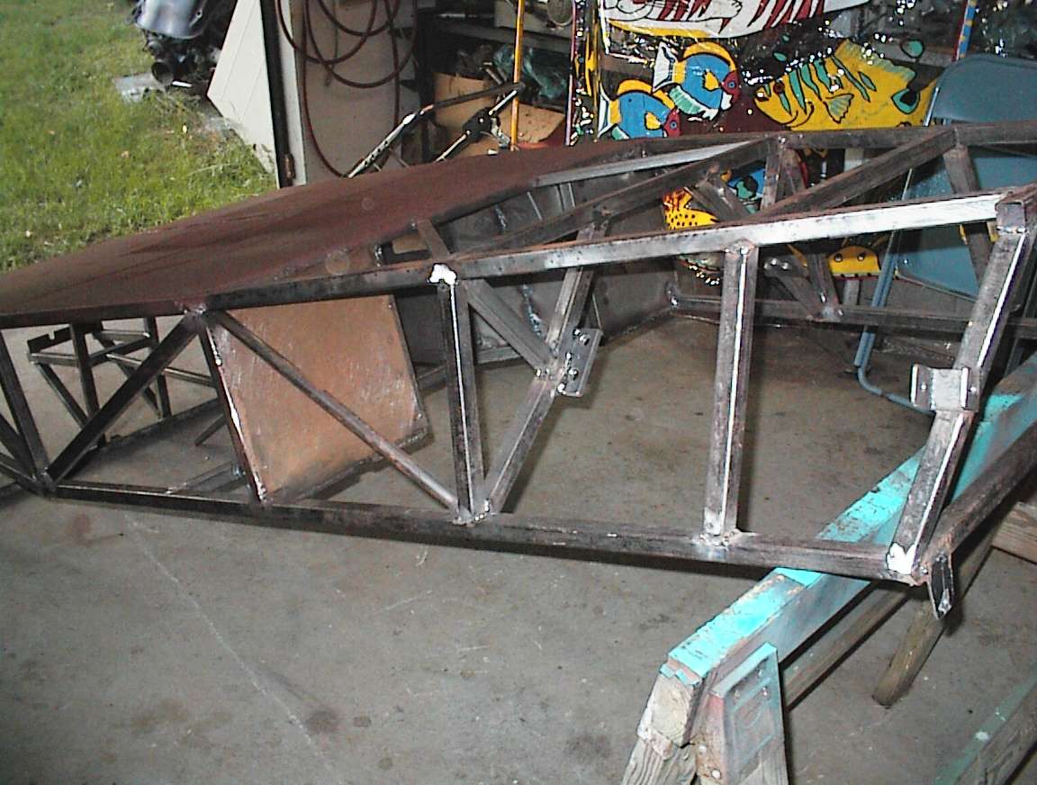 Now we're finishing up all the main structure welding, so we're flipping the
chassis into convenient positions. It's still light enough for one man to
handle.
Now we're finishing up all the main structure welding, so we're flipping the
chassis into convenient positions. It's still light enough for one man to
handle.
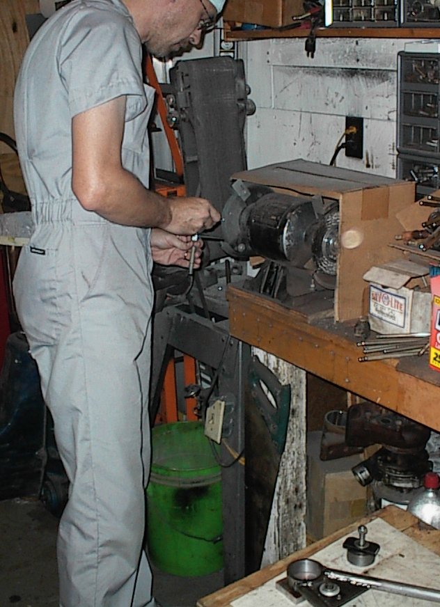
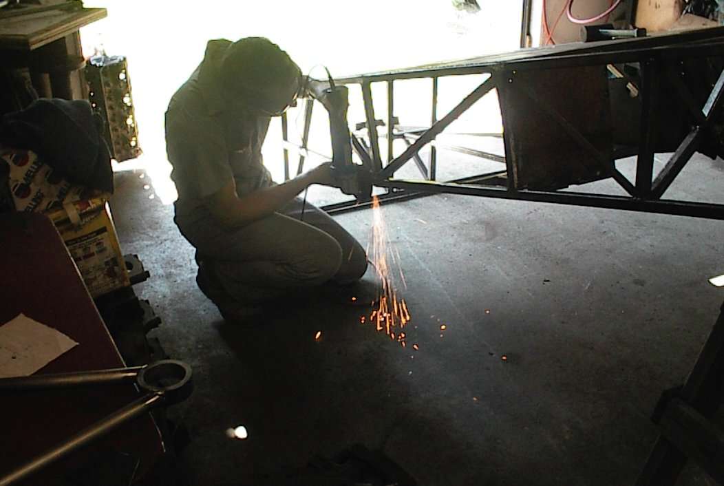 Ron grinding some welds off the tubing joints.
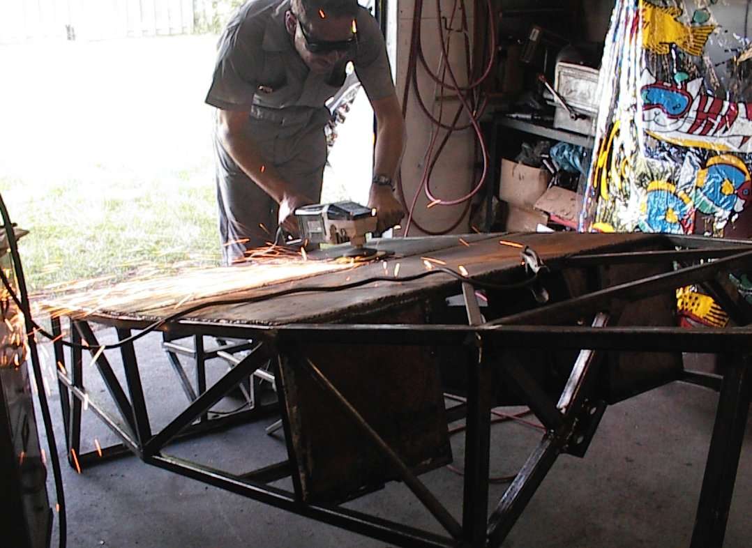 Ron grinding down the seam welds for the floor panels. Since there were three
panels, there was a *lot* of weld bead!
Ron grinding down the seam welds for the floor panels. Since there were three
panels, there was a *lot* of weld bead!
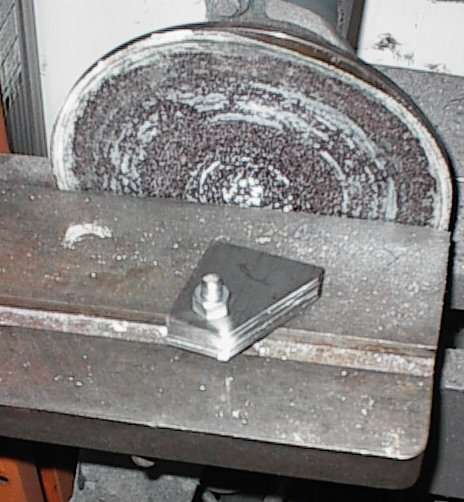 These are the shock absorber brackets that go on the lower A-arm. I ganged
them up for grinding and belt sanding.
These are the shock absorber brackets that go on the lower A-arm. I ganged
them up for grinding and belt sanding.
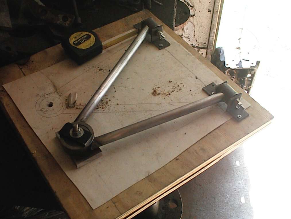 One side of the lower A-arm has already been welded, and it has just been
flipped over. Rigid fixture keeps the arm from distorting during welding.
One side of the lower A-arm has already been welded, and it has just been
flipped over. Rigid fixture keeps the arm from distorting during welding.
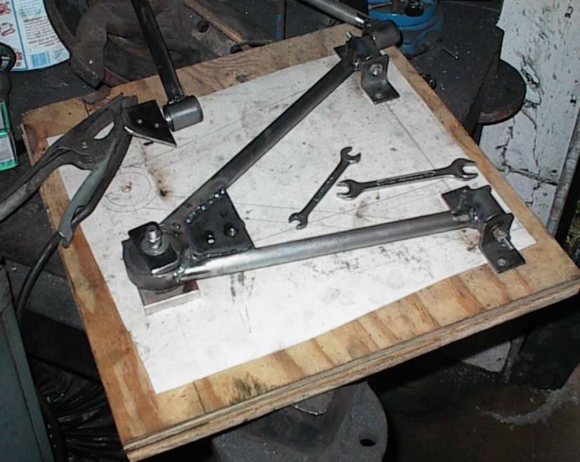 All welded up. Major FUD here, but I'm happy with the result. I had
originally intended to just tack it all together and take it to a Real
Welder(tm), but I was having one of those days when pulling the trigger of the
MIG left beautiful shiny welds.
All welded up. Major FUD here, but I'm happy with the result. I had
originally intended to just tack it all together and take it to a Real
Welder(tm), but I was having one of those days when pulling the trigger of the
MIG left beautiful shiny welds.
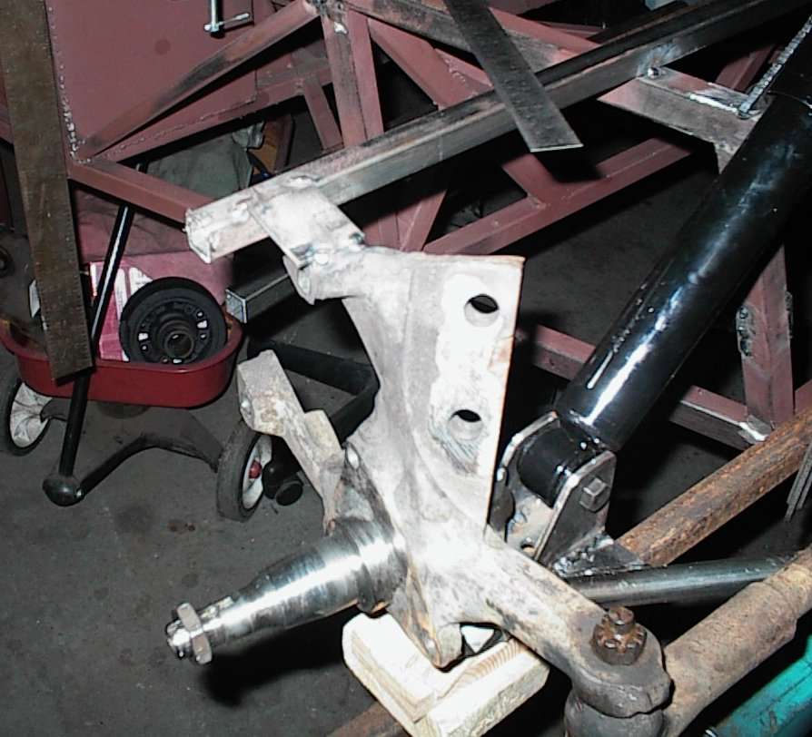
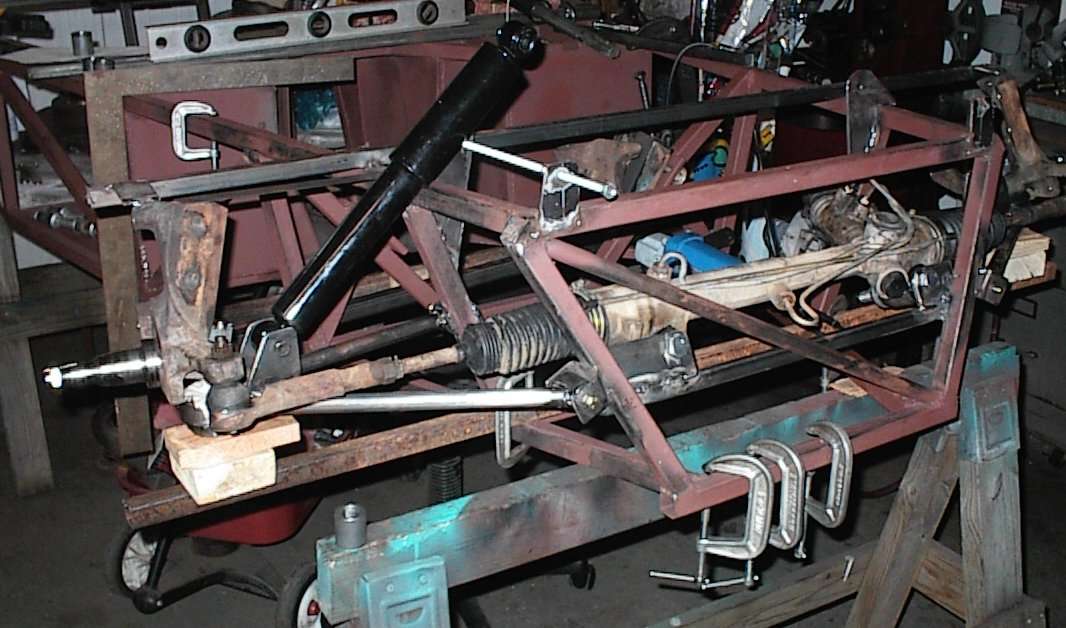 This is a pretty interesting shot. The rack is already bolted to its own
little crossmember. Note how the hydraulic lines just clear. The tabs for the
upper A-arms are in place; the near ones still have the threaded rod bolted
through that kept them lined up for welding. The tube under the lower A-arm
has the arms shimmed up to the correct ride height. The gas shock is fully
extended, but it's still quite long. The application is the rear of a half
ton Chevy pickup; it was the shortest shock we could find that had a loop at
each end.
This is a pretty interesting shot. The rack is already bolted to its own
little crossmember. Note how the hydraulic lines just clear. The tabs for the
upper A-arms are in place; the near ones still have the threaded rod bolted
through that kept them lined up for welding. The tube under the lower A-arm
has the arms shimmed up to the correct ride height. The gas shock is fully
extended, but it's still quite long. The application is the rear of a half
ton Chevy pickup; it was the shortest shock we could find that had a loop at
each end.
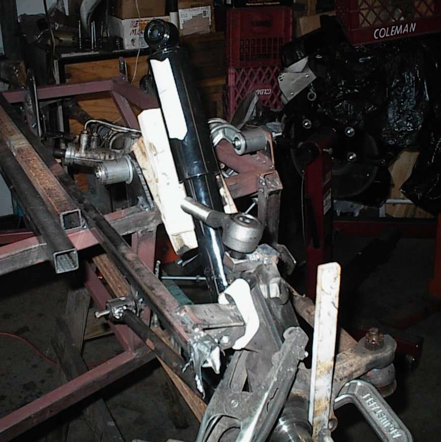
 Vertical bar clamped to spindle; a level tells us when the spindle is
perpendicular to the ground. Then we used a protractor to set the caster.
Vertical bar clamped to spindle; a level tells us when the spindle is
perpendicular to the ground. Then we used a protractor to set the caster.
 3/4" tube tacked to the spindle top keeps it in alignment while we're
monkeying about. We cut the welds with a Dremel when we were done.
3/4" tube tacked to the spindle top keeps it in alignment while we're
monkeying about. We cut the welds with a Dremel when we were done.
 Ron's grinding on something-or-other.
 In this shot, we've started building the spindle adapters. The little blocky
part on top of the spindle has a tapered hole for the ball joint. Later we'll
brace it substantially; for now, it's holding the bits in place.
In this shot, we've started building the spindle adapters. The little blocky
part on top of the spindle has a tapered hole for the ball joint. Later we'll
brace it substantially; for now, it's holding the bits in place.