 The upper ball joint is actually a Mustang tierod end, threaded into a
bushing, with a jam nut on the back side to keep the bushing from turning in
the sleeve. The sleeve is the end of the A-arm. I had bored it on the lathe
before welding up the A-arm, but the welding process warped it enough that the
bushing wouldn't go in, so I honed it back round on the rod machine. I had
machined everything with essentially zero clearance to start with; now it has
.005" or so; it's still okay.
The upper ball joint is actually a Mustang tierod end, threaded into a
bushing, with a jam nut on the back side to keep the bushing from turning in
the sleeve. The sleeve is the end of the A-arm. I had bored it on the lathe
before welding up the A-arm, but the welding process warped it enough that the
bushing wouldn't go in, so I honed it back round on the rod machine. I had
machined everything with essentially zero clearance to start with; now it has
.005" or so; it's still okay.
 The rubber A-arm bushings are from a Triumph Spitfire. I made two tools; one
to press them into the A-arms, and one to remove them.
The rubber A-arm bushings are from a Triumph Spitfire. I made two tools; one
to press them into the A-arms, and one to remove them.
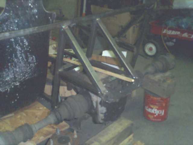
 Upper A-arms in place. Only one side of each A-arm bracket is installed at
the moment; they'll be in double shear when we're done.
Upper A-arms in place. Only one side of each A-arm bracket is installed at
the moment; they'll be in double shear when we're done.
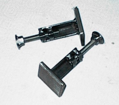
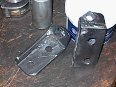 Finished knuckle adapters. These bolt on where the McPherson strut used to
attach.
Finished knuckle adapters. These bolt on where the McPherson strut used to
attach.
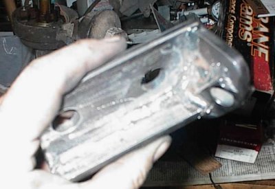 I welded the snot out of them, since they're a critical suspension
component...
I welded the snot out of them, since they're a critical suspension
component...
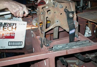
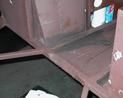 The engine is slid as far back and low as possible. We had to notch this
crossmember and weld a patch over it to get some clearance. Odd angles in the
footwell are to clear the T-5 transmission.
The engine is slid as far back and low as possible. We had to notch this
crossmember and weld a patch over it to get some clearance. Odd angles in the
footwell are to clear the T-5 transmission.
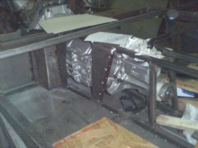
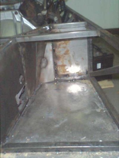 Passenger side footwell. The corner is three pieces, one hammerformed with a
bulge for transmission clearance, one heated and bent for clearance. Side
panel has access holes for fill and drain plugs. Forward panel is ahead of
frame members, for another inch of footroom. The transmission tunnel turned
out to be a major project, trying to vacuum-pack structural members around the
transmission. We'd never before realized how huge a Borg/Warner T-5 is!
Passenger side footwell. The corner is three pieces, one hammerformed with a
bulge for transmission clearance, one heated and bent for clearance. Side
panel has access holes for fill and drain plugs. Forward panel is ahead of
frame members, for another inch of footroom. The transmission tunnel turned
out to be a major project, trying to vacuum-pack structural members around the
transmission. We'd never before realized how huge a Borg/Warner T-5 is!
 Slightly different angle showing multiple panels. Ugly, but we were working
hard for every bit of footroom.
Slightly different angle showing multiple panels. Ugly, but we were working
hard for every bit of footroom.
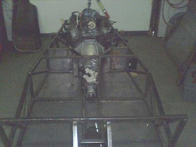 This shot shows the engine offset clearly. It's only one inch, but it looks
like a lot more, for some reason. Besides getting more room for the driver,
it lines the crankshaft up with the pinion on the rear end, which is also
offset one inch to the passenger side.
This shot shows the engine offset clearly. It's only one inch, but it looks
like a lot more, for some reason. Besides getting more room for the driver,
it lines the crankshaft up with the pinion on the rear end, which is also
offset one inch to the passenger side.
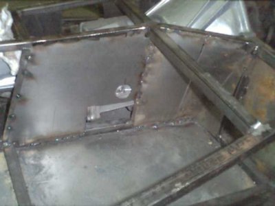
 The driver's side was easier, though we had to add a large bulge to clear the
clutch fork and cable. The forward panel isn't welded in yet. If you look
closely, you can see tapped holes around the edges where the back panel goes -
that one is removable so we can get to the transmission mount, since it's not
accessible from the top or bottom.
The driver's side was easier, though we had to add a large bulge to clear the
clutch fork and cable. The forward panel isn't welded in yet. If you look
closely, you can see tapped holes around the edges where the back panel goes -
that one is removable so we can get to the transmission mount, since it's not
accessible from the top or bottom.
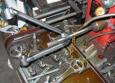
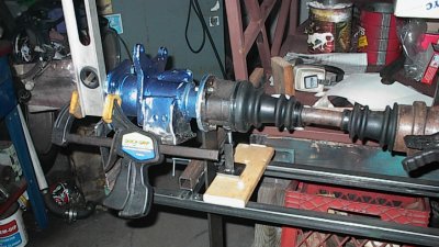
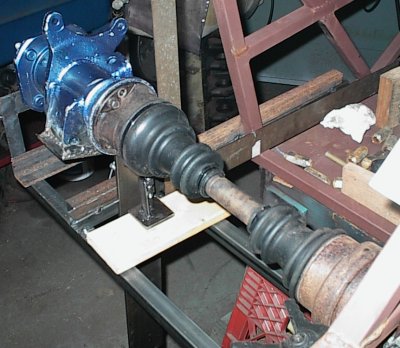
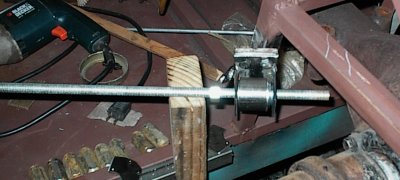
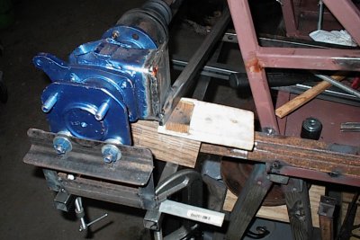
 The stock Mustang steering shaft was sixteen inches too short. I sawed both
ends off so I could splice it with a section of steel tubing.
The stock Mustang steering shaft was sixteen inches too short. I sawed both
ends off so I could splice it with a section of steel tubing.
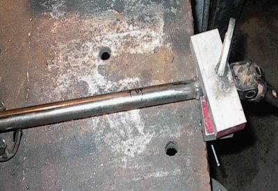 I used aluminum blocks clamped to the tube to try to keep some of the heat
away from the U-joint, which was "sealed for life" and not regreasable. It
never got too hot to touch, amazingly enough.
I used aluminum blocks clamped to the tube to try to keep some of the heat
away from the U-joint, which was "sealed for life" and not regreasable. It
never got too hot to touch, amazingly enough.
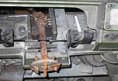
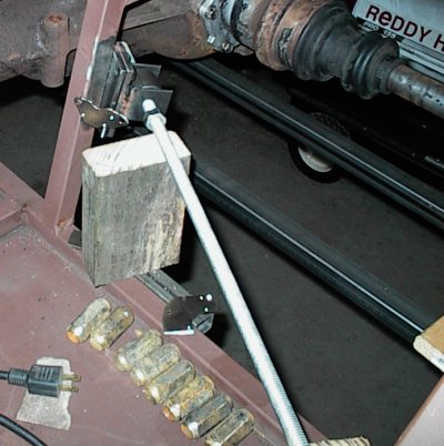
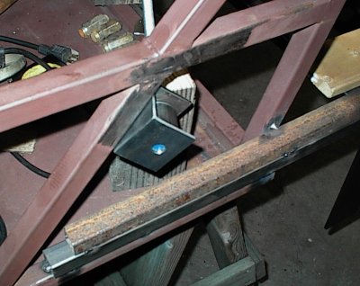
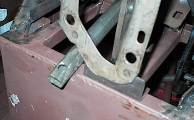 With the rack positioned where it had to be, and the steering column where we
wanted it to be, the end of the column hit the upper chassis rail. We carved
it out with the angle grinder, cut a piece of muffler pipe, welded it in, and
ground it down, for a nicely curved clearance notch.
With the rack positioned where it had to be, and the steering column where we
wanted it to be, the end of the column hit the upper chassis rail. We carved
it out with the angle grinder, cut a piece of muffler pipe, welded it in, and
ground it down, for a nicely curved clearance notch.
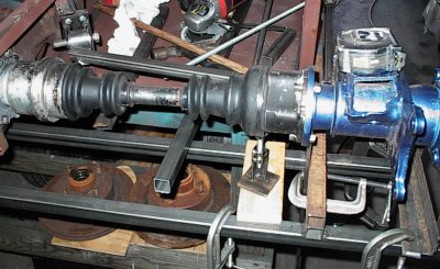
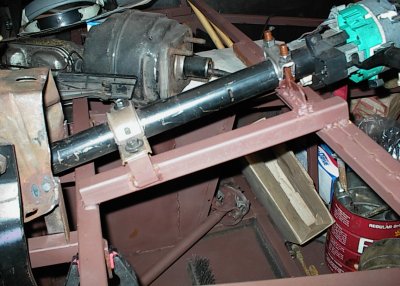 The front support bracket is the stock Mustang part. The lower part of the
column is actually inverted from how it went on a Mustang. I made some tapped
blocks and welded them to the longitudinal rails to secure the column there.
Then, at the other end, I welded a muffler clamp to the rails to support the
column at the wheel end. It's much more rigidly supported than the original
Mustang application!
The front support bracket is the stock Mustang part. The lower part of the
column is actually inverted from how it went on a Mustang. I made some tapped
blocks and welded them to the longitudinal rails to secure the column there.
Then, at the other end, I welded a muffler clamp to the rails to support the
column at the wheel end. It's much more rigidly supported than the original
Mustang application!
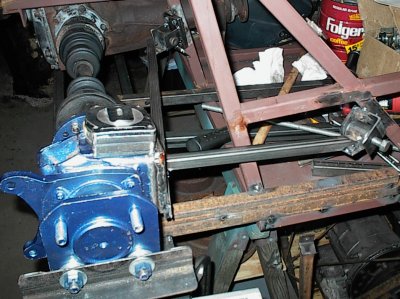
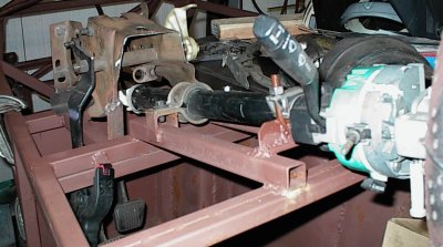 This shot shows the supports a bit better. Yes, it's a tilt column. "Free is
a quality overcoming many faults."
This shot shows the supports a bit better. Yes, it's a tilt column. "Free is
a quality overcoming many faults."
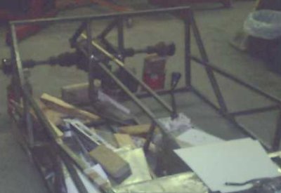
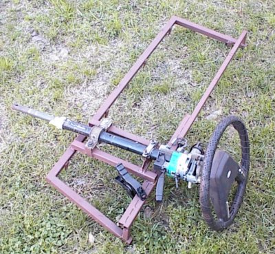 Scuttle assembly with column. Drilled tabs hang down from the bottom, six
bolts hold it to the main chassis, so it's easily removable. The dash and
windshield will be attached to this part later.
Scuttle assembly with column. Drilled tabs hang down from the bottom, six
bolts hold it to the main chassis, so it's easily removable. The dash and
windshield will be attached to this part later.
 Front panel for pedal box. It will get welded to the chassis, with the brake
booster bolted through it to the pedal bracket. A large holesaw made the
center hole.
Front panel for pedal box. It will get welded to the chassis, with the brake
booster bolted through it to the pedal bracket. A large holesaw made the
center hole.
 Tapped strip on top of chassis rail is to bolt down the pedal box cover, which
we haven't built yet. This is the pedal box from the Mustang, sawed down to a
fraction of its former size, with some support brackets welded here and there
to attach it to the chassis. We decided it didn't need to be removable, since
we could pull the cover and access all its naughty bits from the engine
compartment.
Tapped strip on top of chassis rail is to bolt down the pedal box cover, which
we haven't built yet. This is the pedal box from the Mustang, sawed down to a
fraction of its former size, with some support brackets welded here and there
to attach it to the chassis. We decided it didn't need to be removable, since
we could pull the cover and access all its naughty bits from the engine
compartment.
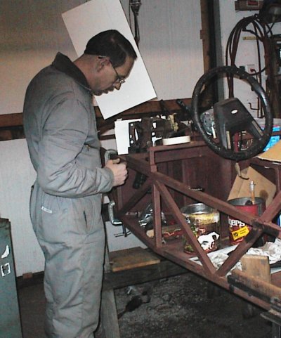 Ron is making cardboard templates for the box cover. Cardboard is your friend
when doing sheet metal work!
Ron is making cardboard templates for the box cover. Cardboard is your friend
when doing sheet metal work!
 The center spine narrows toward the rear, again for extra hiproom.
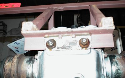
 Strong bracket to hold the differential up. There's provision on the diff
snout for a torque arm; we'll fabricate one to go up to the transmission
tailshaft, which will eliminate the bending load that tries to tweak the rear
firewall every time you punch the throttle. Well, it'll spread it through
half the length of the car, which is better than the few inches of the usual
four link.
Strong bracket to hold the differential up. There's provision on the diff
snout for a torque arm; we'll fabricate one to go up to the transmission
tailshaft, which will eliminate the bending load that tries to tweak the rear
firewall every time you punch the throttle. Well, it'll spread it through
half the length of the car, which is better than the few inches of the usual
four link.
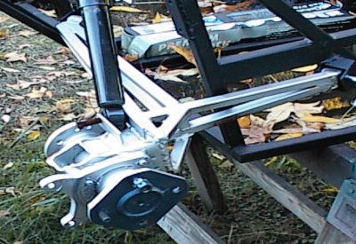
 The Nissan rear attached to its stock subframe with studs through holes. I
used slots instead of holes, so the diff could drop straight down instead of
having to slide forward before coming down. Small Allen screw on backing
plate keeps everything in place when nuts are loosened. We're trying hard to
make this thing maintenance-friendly.
The Nissan rear attached to its stock subframe with studs through holes. I
used slots instead of holes, so the diff could drop straight down instead of
having to slide forward before coming down. Small Allen screw on backing
plate keeps everything in place when nuts are loosened. We're trying hard to
make this thing maintenance-friendly.
 The Nissan's semi-trailing arms were huge and heavy. We paid a local muffler
shop a few bucks to whack the hubs off with their plasma cutter; it saved a
lot of angle grinder work. After neatening the cuts up (with the angle
grinder...), we cut some steel plates to weld to the hubs. These are where
most of the new semi-trailing arm tubes will attach. We didn't feel like
disassembling the hubs, so we submerged them in water while welding to keep
from cooking the grease and seals. This worked astoundingly well; the hubs
never got more than warm to the touch!
The Nissan's semi-trailing arms were huge and heavy. We paid a local muffler
shop a few bucks to whack the hubs off with their plasma cutter; it saved a
lot of angle grinder work. After neatening the cuts up (with the angle
grinder...), we cut some steel plates to weld to the hubs. These are where
most of the new semi-trailing arm tubes will attach. We didn't feel like
disassembling the hubs, so we submerged them in water while welding to keep
from cooking the grease and seals. This worked astoundingly well; the hubs
never got more than warm to the touch!
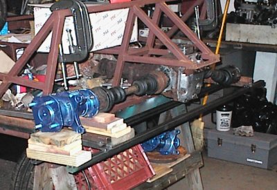
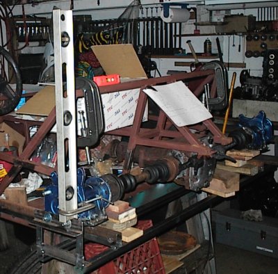
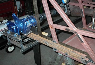
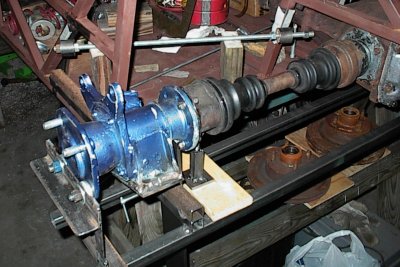
 Half of the work we've done so far has been alignment fixturing. Here, I've
tack welded some tubes extending back from the main frame rails, then run some
transverse tubes to make an accurate work surface to build the rear
suspension. I'm building it in place, right on the car.
Half of the work we've done so far has been alignment fixturing. Here, I've
tack welded some tubes extending back from the main frame rails, then run some
transverse tubes to make an accurate work surface to build the rear
suspension. I'm building it in place, right on the car.
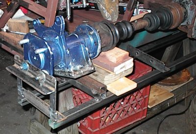
 Hub and stacks of shims
 More fixturing. I made these brackets to hold the hubs at the correct ride
height.
More fixturing. I made these brackets to hold the hubs at the correct ride
height.
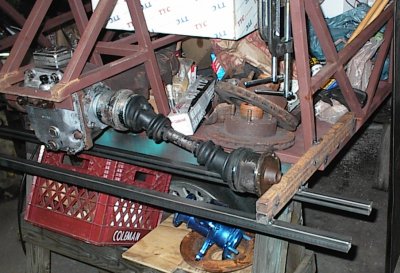
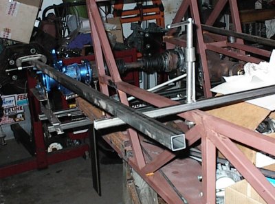 I used some long pieces of square tubing to align them lengthwise,
and adjusted them inboard a bit on the variable-length halfshafts so there was
adequare tire clearance and halfshaft travel.
I used some long pieces of square tubing to align them lengthwise,
and adjusted them inboard a bit on the variable-length halfshafts so there was
adequare tire clearance and halfshaft travel.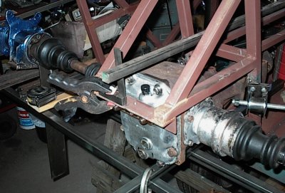 Then I tack welded them into
place so they couldn't get bumped out of alignment.
Then I tack welded them into
place so they couldn't get bumped out of alignment.
 Checking the camber. We decided to build zero camber into the suspension at
rest, and go with camber gain in bump with the semi-trailing arm geometry.
Paper clamped to differential bracket is notes and sketches for the rear end.
Checking the camber. We decided to build zero camber into the suspension at
rest, and go with camber gain in bump with the semi-trailing arm geometry.
Paper clamped to differential bracket is notes and sketches for the rear end.
 Stacks of shims were a pain in the tail. I decided I needed some special
jacks to support the inboard ends of the hubs.
Stacks of shims were a pain in the tail. I decided I needed some special
jacks to support the inboard ends of the hubs.
 A while later, I had jacks. Tools are good karma.
 Jacks now adjust camber...
 The last thing is to make sure both hubs are perpendicular. I measured back
from the rear chassis rail, which is one of the reference points. A T-square
worked just fine for this.
The last thing is to make sure both hubs are perpendicular. I measured back
from the rear chassis rail, which is one of the reference points. A T-square
worked just fine for this.
 Everything matched on both sides, camber okay, toe okay. We're ready to rock!
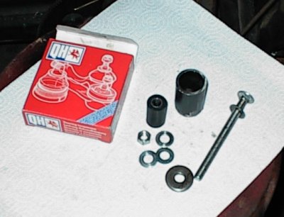
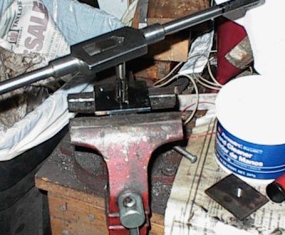
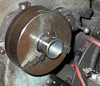 The semi-trailing arms needed four bushings. Whack some more tubing off in
the bandsaw, bore in the lathe to match the bushings we picked out of the
catalog at NAPA.
The semi-trailing arms needed four bushings. Whack some more tubing off in
the bandsaw, bore in the lathe to match the bushings we picked out of the
catalog at NAPA.
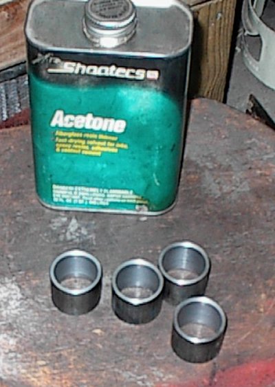 Finished bushings.
 I glued some scrap wood together, roughed them round on the bandsaw, and
drilled holes in the middle.
I glued some scrap wood together, roughed them round on the bandsaw, and
drilled holes in the middle.
 Then I turned them on the lathe...
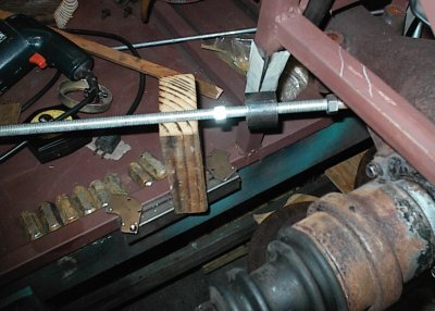
 And they now slide into the bushings. More fixturing; we're going to be
welding the trailing arms up in place, and we can't use the rubber bushings,
or they'd just catch fire.
And they now slide into the bushings. More fixturing; we're going to be
welding the trailing arms up in place, and we can't use the rubber bushings,
or they'd just catch fire.
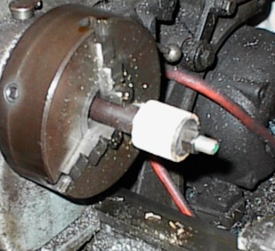
 This is the semi-trailing arm axis. Threaded rod holds the bushings in the
proper positions.
This is the semi-trailing arm axis. Threaded rod holds the bushings in the
proper positions.
 Bushing sleeve in position.
 I made some tapped plates to weld to the vertical chassis members, then pickup
plates to hold the bushings. The pickup plates will get additional
triangulation bracing later. The removable pickup plates weren't absolutely
necessary... but the member they're attaching to is part of the rear firewall
support, and there will be steel sheet welded across. We could have put an
access hole in the firewall, or required that the rear end be dropped so the
bolts could come out in that direction, but it seemed a lot simpler just to
make the brackets removable.
I made some tapped plates to weld to the vertical chassis members, then pickup
plates to hold the bushings. The pickup plates will get additional
triangulation bracing later. The removable pickup plates weren't absolutely
necessary... but the member they're attaching to is part of the rear firewall
support, and there will be steel sheet welded across. We could have put an
access hole in the firewall, or required that the rear end be dropped so the
bolts could come out in that direction, but it seemed a lot simpler just to
make the brackets removable.
 Ready to tack them into position. 2x4 blocks were cut to the correct height
to hold the rods without shimming.
Ready to tack them into position. 2x4 blocks were cut to the correct height
to hold the rods without shimming.
 Now I'm building the front bushing boxes. Since there's no room for a nut,
I'm making a doubler plate and tapping it, so we can just use a bolt.
Now I'm building the front bushing boxes. Since there's no room for a nut,
I'm making a doubler plate and tapping it, so we can just use a bolt.
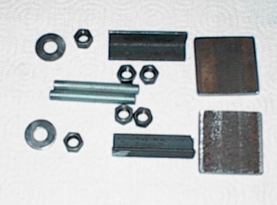
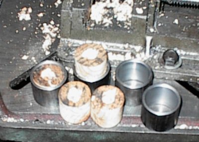
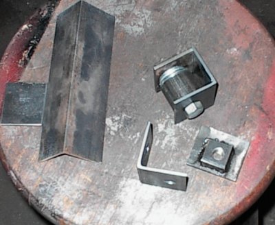 Assembled and unassembled bushing boxes. Stack of washers compensates for the
flange on the rubber bushing; the boxes might distort during welding, and I
don't want the threads and holes to get out of alignment.
Assembled and unassembled bushing boxes. Stack of washers compensates for the
flange on the rubber bushing; the boxes might distort during welding, and I
don't want the threads and holes to get out of alignment.
 Front bushing box in position. A tack weld, and it'll be fine for now.
Later, we'll add considerable bracing.
Front bushing box in position. A tack weld, and it'll be fine for now.
Later, we'll add considerable bracing.
 1/2" x .060" CRS square tubing, sliced at the ends to line up with the bushing
sleeve and the welded plate on the hub. Fabrication begins!
1/2" x .060" CRS square tubing, sliced at the ends to line up with the bushing
sleeve and the welded plate on the hub. Fabrication begins!
 Now we bring a tube back from the front bushing sleeve. Later a tube will go
on the top. These two members hold brake torque and wheel thrust loads.
Now we bring a tube back from the front bushing sleeve. Later a tube will go
on the top. These two members hold brake torque and wheel thrust loads.
 Two of four tubes; there will be two on the top and two on the bottom, in a
long pyramid, to take toe-in and camber loads.
Two of four tubes; there will be two on the top and two on the bottom, in a
long pyramid, to take toe-in and camber loads.
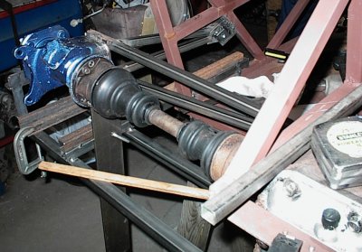
 Bare hub and trailing arm - 22 pounds. Not bad at all.
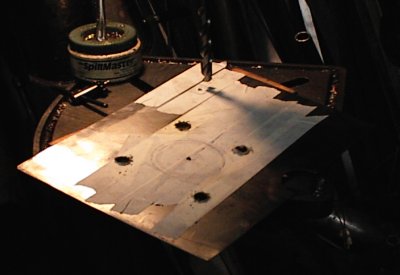
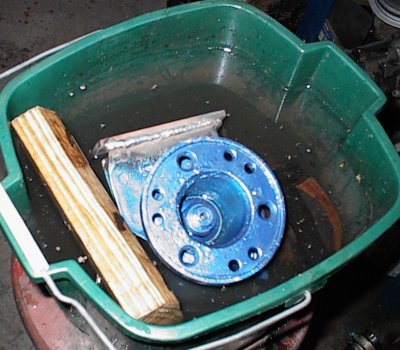
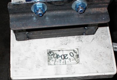
 The front hubs are Ford, and we're re-using the Mustang's wheels, so we needed
to re-drill the Nissan rear hubs. I turned a chunk of 1/2" aluminum plate on
the lathe, marked out the 4-on-4.25" Ford pattern, and drilled.
The front hubs are Ford, and we're re-using the Mustang's wheels, so we needed
to re-drill the Nissan rear hubs. I turned a chunk of 1/2" aluminum plate on
the lathe, marked out the 4-on-4.25" Ford pattern, and drilled.
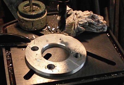
 Small drilled and tapped holes in the sides...
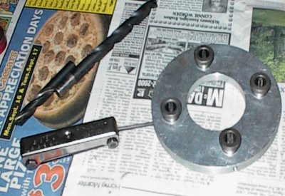 Hold four expensive carbide drill bushings. Drill bit to the far left is the
correct size for the Nissan studs' knurl.
Hold four expensive carbide drill bushings. Drill bit to the far left is the
correct size for the Nissan studs' knurl.
 Doubling nuts and driving the studs out...
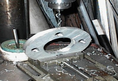
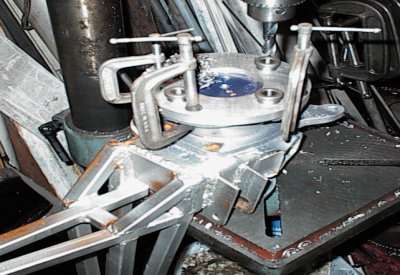 ...then redrilling the flanges. This was a five minute job after hours of
tool building. You can see some of the triangulated control arm in this shot.
...then redrilling the flanges. This was a five minute job after hours of
tool building. You can see some of the triangulated control arm in this shot.
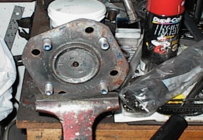 Finished hub, Ford bolt circle. We'll have to redrill the brake rotors next.
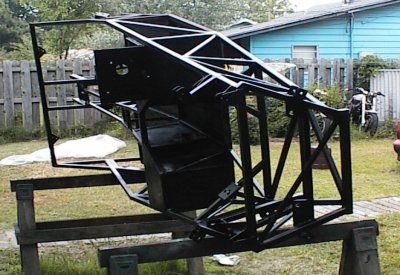
 Finishing up the chassis. You can see where we've doubled up on the tubes for
the front semi-trailing arm brackets. Later we'll weld a sheet metal panel in
that non-triangulated area as a stressed web.
Finishing up the chassis. You can see where we've doubled up on the tubes for
the front semi-trailing arm brackets. Later we'll weld a sheet metal panel in
that non-triangulated area as a stressed web.
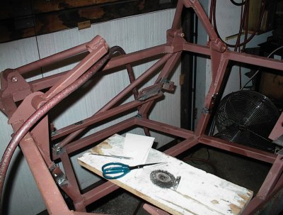
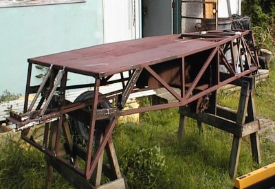
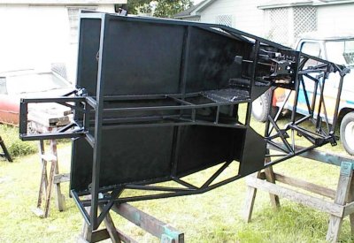 Painting the chassis. It's nearly complete now. The side panels still aren't
attached - they'll be welded on last, along with the rear firewall and a few
other bits.
Painting the chassis. It's nearly complete now. The side panels still aren't
attached - they'll be welded on last, along with the rear firewall and a few
other bits.
 You can see how we varied from the Lotus/Locost design quite a bit.
Basically, wherever adding more tubing or welding panels in would add
strength, we did it. The chassis weighs 175 or 200 pounds; the two of us can
carry it about, but it's heavy.
You can see how we varied from the Lotus/Locost design quite a bit.
Basically, wherever adding more tubing or welding panels in would add
strength, we did it. The chassis weighs 175 or 200 pounds; the two of us can
carry it about, but it's heavy.
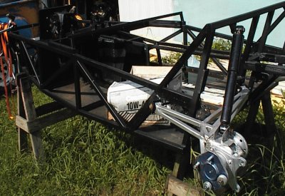 Nice shot of completed semi-trailing arm. Upper shock bracket isn't in place
yet.
Nice shot of completed semi-trailing arm. Upper shock bracket isn't in place
yet.
All we need now is a few days of round tuits, and we'll be ready to go.